Eureka AIR delivers breakthrough ideas for toughest innovation challenges, trusted by R&D personnel around the world.

Microfluidic chip and application thereof

A microfluidic chip and microchannel technology, applied in the field of microfluidics, can solve the problems of single nephron structure and cannot effectively simulate blood purification, etc., and achieve the effect of easy maintenance.

Inactive Publication Date: 2018-03-23
DALIAN UNIV OF TECH
View PDF7 Cites 5 Cited by
  • Summary
  • Abstract
  • Description
  • Claims
  • Application Information

AI Technical Summary

Problems solved by technology

[0006] Existing chips for simulating the material exchange membrane structure of the kidney system mainly include three-layer single-channel sandwich structures. For example, Ingber uses a three-layer single-channel sandwich structure to simulate the membrane structure formed by glomerular endothelial cells-podocytes , In another work, Ingber used this structure chip to simulate the single-layer channel chip of renal tubule structure. The membranous structure formed by the vascular endothelial cells of the glomerulus-podocytes, these structural units can only provide a material exchange area for the two fluids, and cannot effectively construct the structure of the glomeruli and renal tubules on the chip at the same time, thus The simulated nephron has a single structure and cannot effectively simulate the process of blood purification

Method used


Image

  • Microfluidic chip and application thereof
  • Microfluidic chip and application thereof
  • Microfluidic chip and application thereof

Examples


Embodiment 1

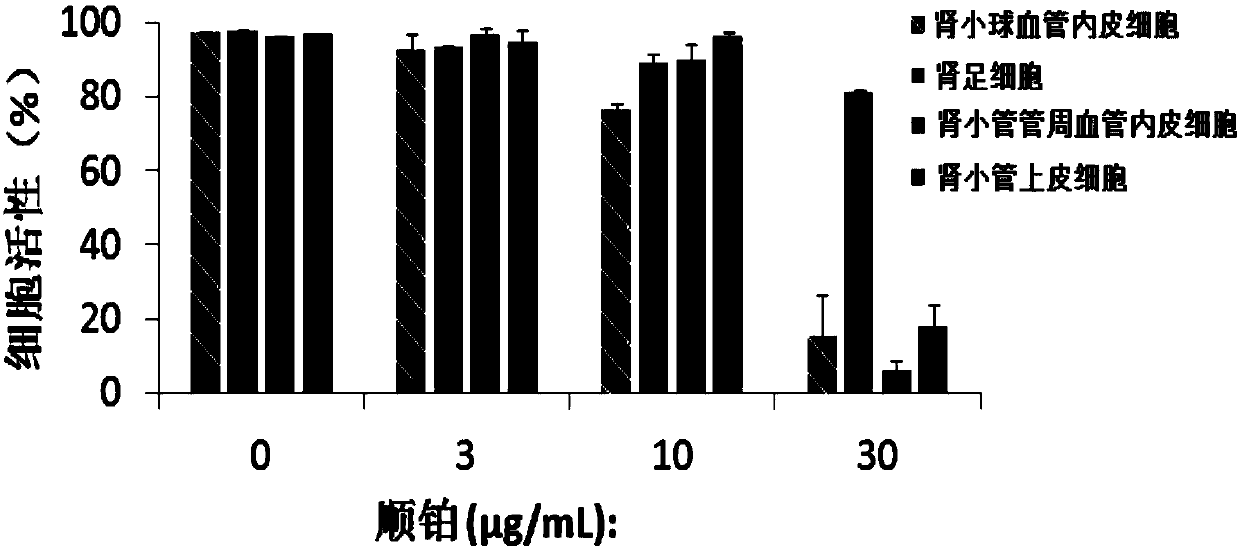
[0020] Take the nephron chip to detect the polar toxicity of different concentrations of cisplatin on nephron cells as an example, as shown in the attached image 3As shown, 0μg / ml, 3μg / ml, 10μg / ml, and 30μg / ml cisplatin were added to the blood pole inlet. After 24 hours, it can be observed that when 30μg / ml cisplatin is added to the system, the glomerular vascular endothelial cells , renal podocytes, renal tubular epithelial cell activity decreased significantly, indicating that 30μg / ml cisplatin has obvious toxicity to glomerular vascular endothelial cells, renal podocytes, and renal tubular epithelial cells.

Embodiment 2

[0022] Take the nephron chip to detect the polar toxicity of doxorubicin at 1.25 μg / ml to nephron cells as an example, as shown in the attached Figure 4 As shown, after adding 1.25 μg / ml doxorubicin at the blood pole inlet, after 48 hours, it can be observed that the activity of glomerular vascular endothelial cells, renal podocytes, and peritube vascular endothelial cells decreased significantly, indicating that in 48 hours , 1.25μg / ml doxorubicin has obvious toxicity to glomerular vascular endothelial cells, renal podocytes and peritubular vascular endothelial cells, but has little effect on renal tubular epithelial cells.


PUM


Abstract

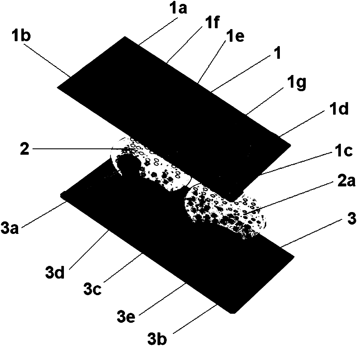
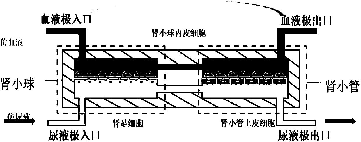
The invention relates to the technical field of microfluidics and provides a microfluidic chip and an application thereof. The microfluidic chip comprises an upper substrate, a lower substrate, a first porous membrane and a second porous membrane, wherein a first liquid inlet, a second liquid inlet, a first liquid outlet, a second liquid outlet, a first chamber, a second chamber and a first microchannel are arranged on the upper substrate; the second liquid inlet, the first chamber, the second chamber and the second liquid outlet are sequentially communicated through the first microchannel; the lower substrate is provided with a third liquid inlet, a third liquid outlet, a third chamber, a fourth chamber and a second microchannel, and the third liquid inlet, the third chamber, the fourth chamber and the third liquid outlet are sequentially communicated through a second microchannel. According to the microfluidic chip, the four chambers are formed, upper fluid and lower fluid can be subjected to material exchange twice on porous membranes separating the four chambers, so that the blood purification process of glomerular filtration and tubular secretion and reabsorption of renal units can be simulated with high simulation degree.

Description

technical field [0001] The invention relates to a microfluidic chip and its application, belonging to the field of microfluidic technology. Background technique [0002] Microfluidics, also known as Lab-on-a-chip, is a science and technology for manipulating fluids in micron-scale space, which can reduce the basic functions of biological and chemical laboratories to one On a chip of several square centimeters, it is one of the most important cutting-edge technologies in the 21st century. It is considered to be the key technology to solve the key problems such as high R&D costs and long cycle of innovative drugs, cosmetics and health products, and to innovate the original technology system. We are facing great development opportunities and challenges. [0003] Organ on a chip is a subclass of microfluidic chip, which is a bionic technology that simulates organs by culturing one or more functional cells in a sheet of several square centimeters. The "organs" in the game are v...

Claims


Application Information

Patent Timeline
Patent Type & Authority Applications(China)
IPC IPC(8): C12M3/00
CPCC12M23/16C12M25/04C12M35/08
Inventor 罗勇曲玥阳安凡高志刚赵伟杰林炳承
Owner DALIAN UNIV OF TECH
Why Eureka
Eureka Blog
Learn More