
Aluminizer conveying device and stamping press comprising alumite conveying device

A conveying device, anodized aluminum technology, applied in the field of hot stamping machines, can solve the problems of the influence of the diameter and width of the anodized aluminum foil, the small storage capacity of the anodized aluminum foil, and the cumbersome process, and achieve the effects of reducing the number of times, shortening the time, and simple replacement.

Pending Publication Date: 2018-03-23
MASTERWORK GROUP CO LTD
View PDF0 Cites 1 Cited by
  • Summary
  • Abstract
  • Description
  • Claims
  • Application Information

AI Technical Summary

Problems solved by technology

Therefore, the following problems arise: when the anodized aluminum needs to be replaced, the operator must first turn off the hot stamping machine, then cut off a small amount of anodized aluminum inside the machine, then pull the remaining anodized aluminum out of the machine, and replace it with a new one outside the machine. aluminum
The whole process is very cumbersome, and the hot stamping machine needs to be shut down for a long time during the replacement of the anodized aluminum
At the same time, due to the internal space and load-bearing limitations of the machine, the roll diameter and width of the anodized aluminum foil are affected to a certain extent, resulting in a small storage capacity of the anodized aluminum foil inside the machine and need to be replaced frequently

Method used


Image

  • Aluminizer conveying device and stamping press comprising alumite conveying device
  • Aluminizer conveying device and stamping press comprising alumite conveying device
  • Aluminizer conveying device and stamping press comprising alumite conveying device

Examples


Embodiment Construction

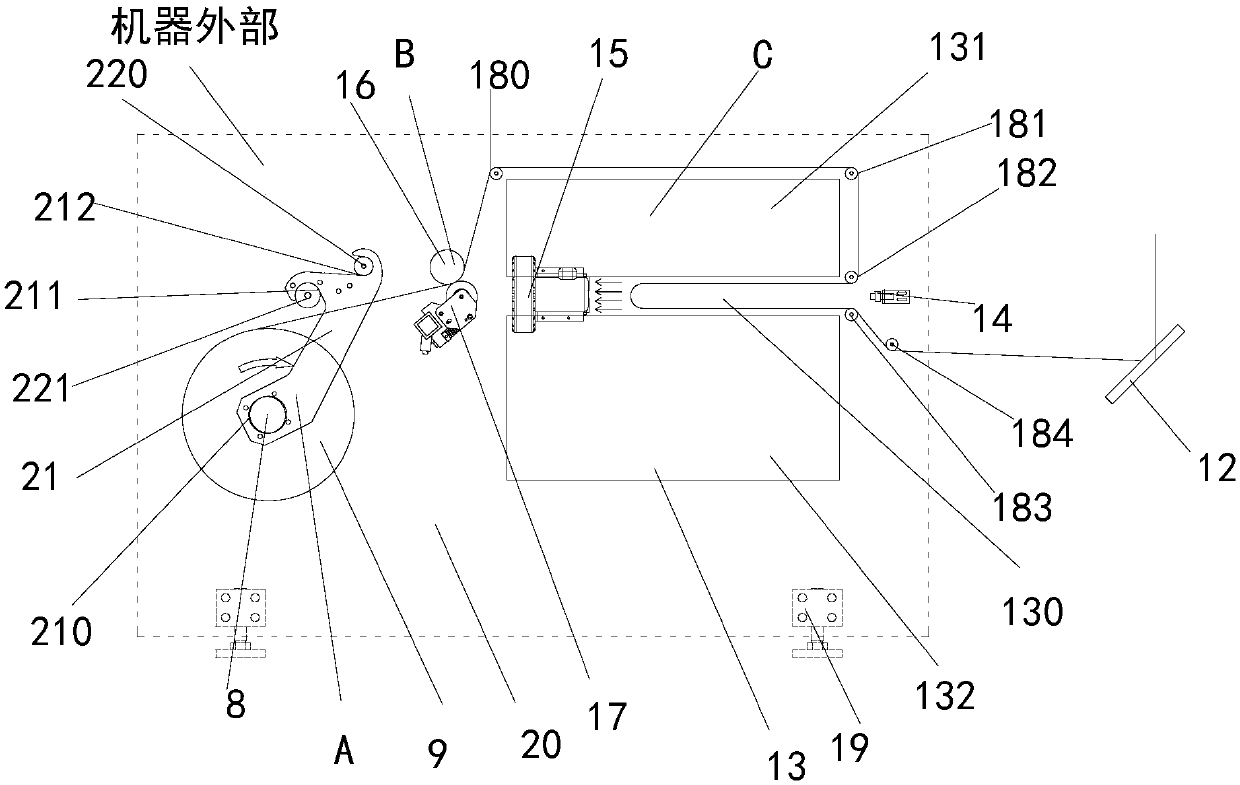
[0018] In order to make the purpose, technical solution and advantages of the present invention clearer, the technical solution of the present application will be clearly and completely described below in conjunction with specific embodiments of the present invention and corresponding drawings. Apparently, the described embodiments are only some of the embodiments of the present application, rather than all the embodiments. Based on the embodiments in this application, all other embodiments obtained by persons of ordinary skill in the art without making creative efforts belong to the scope of protection of this application. The technical solutions provided by various embodiments of the present application will be described in detail below in conjunction with the accompanying drawings.

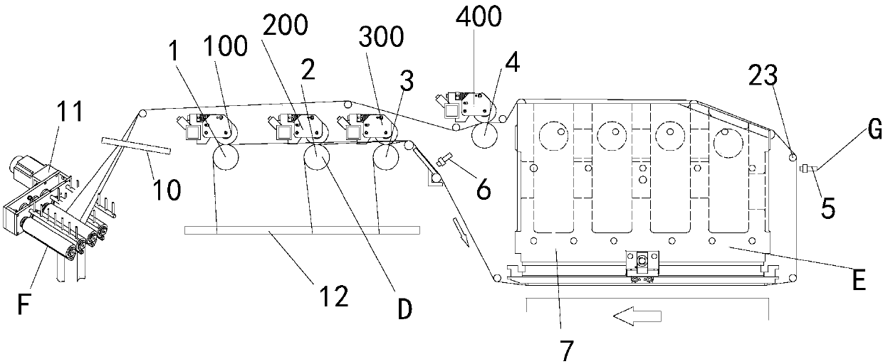
[0019] figure 1 It is a structural diagram of an anodized aluminum transmission device according to an embodiment of the present application. Such as figure 1 As shown, the present applicati...


PUM


Abstract

The invention relates to an aluminizer conveying device and a stamping press comprising the aluminizer conveying device. The aluminizer conveying device comprises a substrate, a fixing assembly, a transmission assembly, a storage assembly, a distance detecting unit and an aluminum foil coil. The aluminum foil coil is mounted on the fixing assembly. The fixing assembly is fixed on the left side ofthe substrate. The storage assembly is fixed on the right side of the substrate. The transmission assembly is fixed at the periphery of the storage assembly. The distance detecting unit is fixed on the right side of the storage assembly. Aluminum foils are conveyed by the fixing assembly and conveyed into the storage assembly through the transmission assembly for vacuum storage; the distance detecting unit detects the depth of the stored aluminum foils, and deviation of aluminum foil conveying accuracy due to inertia problem caused by the lack of storage is avoided; and finally, aluminizer isconveyed to the stamping press through the transmission assembly. According to the aluminizer conveying device and the stamping press comprising the aluminizer conveying device, the aluminizer can bestored and conveyed at the exterior of the stamping press, the replacing time at every time is shortened while the replacing frequency of the aluminum coils is reduced, and the working efficiency of the stamping press is improved accordingly.

Description

technical field [0001] The invention relates to the field of hot stamping machines, in particular to an anodized aluminum transmission device and a hot stamping machine including the same. Background technique [0002] Hot stamping refers to the process of hot stamping anodized aluminum foil onto the surface of the substrate under a certain temperature and pressure. But in the existing hot stamping process, the storage and control of anodized aluminum are inside the hot stamping machine. Therefore, the following problems arise: when the anodized aluminum needs to be replaced, the operator must first turn off the hot stamping machine, then cut off a small amount of anodized aluminum inside the machine, then pull the remaining anodized aluminum out of the machine, and replace it with a new one outside the machine. aluminum. After the replacement is completed, push the anodized aluminum into the machine, and then glue the anodized aluminum to the inside of the machine to comp...

Claims


Application Information

Patent Timeline
Patent Type & Authority Applications(China)
IPC IPC(8): B41F19/06
CPCB41F19/068B41P2219/23B41P2219/20
Inventor 董晓岭韦树远陈光周光伟祃普元李志合宋攀何文森李佳禾
Owner MASTERWORK GROUP CO LTD
Learn More