
Novel efficient shutter die feeding device

A technology for forming molds and feeding devices, which is applied in the field of stamping molds, can solve the problems of material waste, difficulty in forming, and difficulty in rolling, etc., and achieve the effects of small molds, cost savings, and good rolling effects

Inactive Publication Date: 2018-03-23
TIANJIN BOLIXIN HARDWARE PROD
View PDF0 Cites 0 Cited by
  • Summary
  • Abstract
  • Description
  • Claims
  • Application Information

AI Technical Summary

Problems solved by technology

[0002] Stamping die is the main production method of hardware forming. According to the production and processing requirements of different hardware parts, different forms are designed to achieve the purpose. The commonly used dies are divided into progressive dies, compound dies and single dies. The main working forms Roughly the same, design the layout and the corresponding convex and concave molds according to different needs, and the other parts are traditional standard parts. Although it is easy to replace during use, it also limits the design ideas of the mold. For our common doors and windows. , the accuracy of stamping and rolling is not high, only good coordination is required. On the one hand, the form design of commonly used progressive dies and composite dies limits the design ideas. According to the traditional method, the layout is often long and difficult to form. On the other hand, Due to the limitation of direction, etc., it is difficult to roll round, and there are many processes, which often result in longer molds and waste of materials.

Method used


Image

  • Novel efficient shutter die feeding device
  • Novel efficient shutter die feeding device
  • Novel efficient shutter die feeding device

Examples


Embodiment Construction

[0030] It should be noted that, in the case of no conflict, the embodiments of the present invention and the features in the embodiments can be combined with each other.

[0031] In describing the present invention, it should be understood that the terms "center", "longitudinal", "transverse", "upper", "lower", "front", "rear", "left", "right", " The orientations or positional relationships indicated by "vertical", "horizontal", "top", "bottom", "inner" and "outer" are based on the orientations or positional relationships shown in the drawings, and are only for the convenience of describing the present invention and Simplified descriptions, rather than indicating or implying that the device or element referred to must have a particular orientation, be constructed and operate in a particular orientation, and thus should not be construed as limiting the invention. In addition, the terms "first", "second", etc. are used for descriptive purposes only, and should not be interpreted...


PUM


Abstract

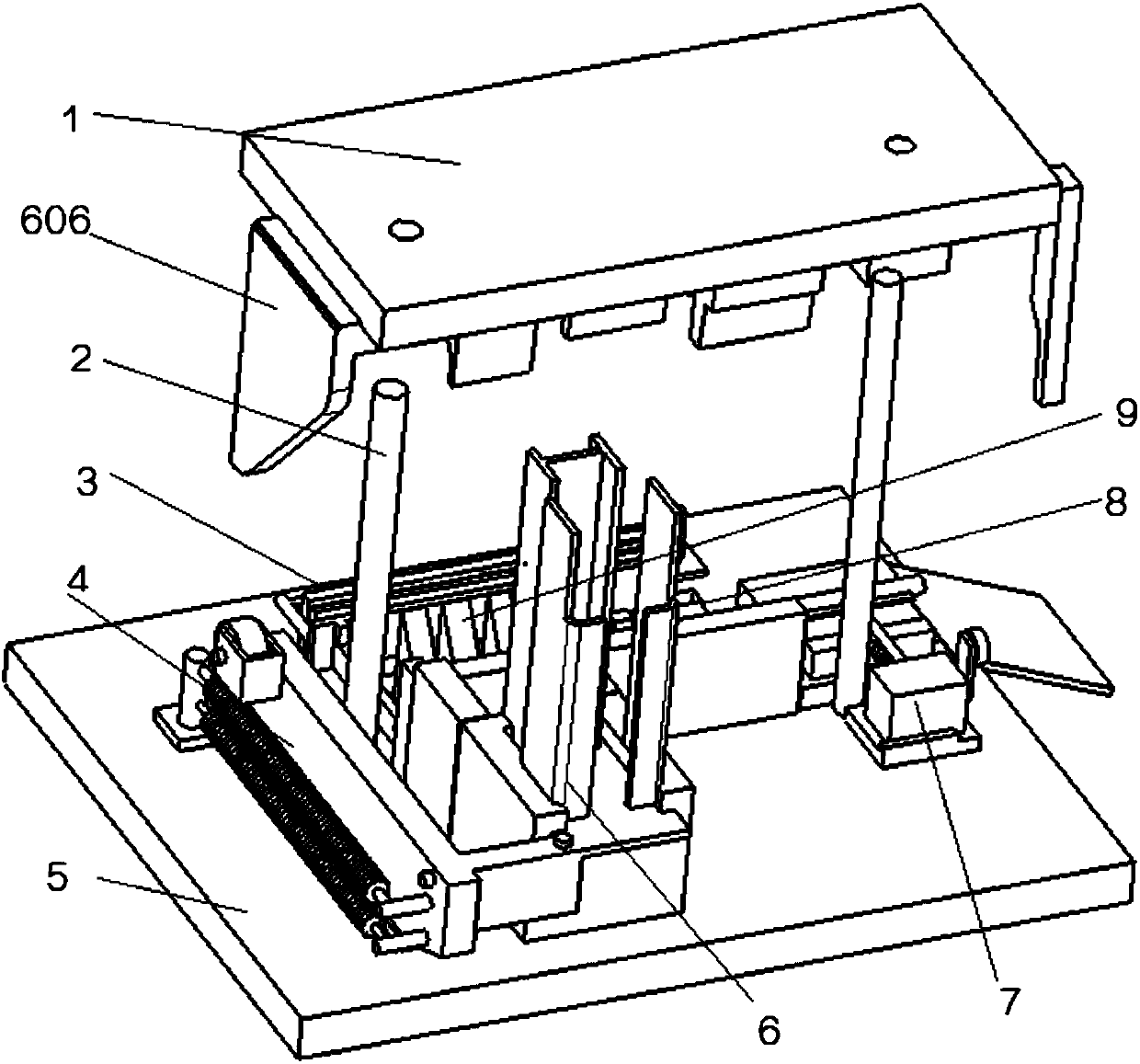
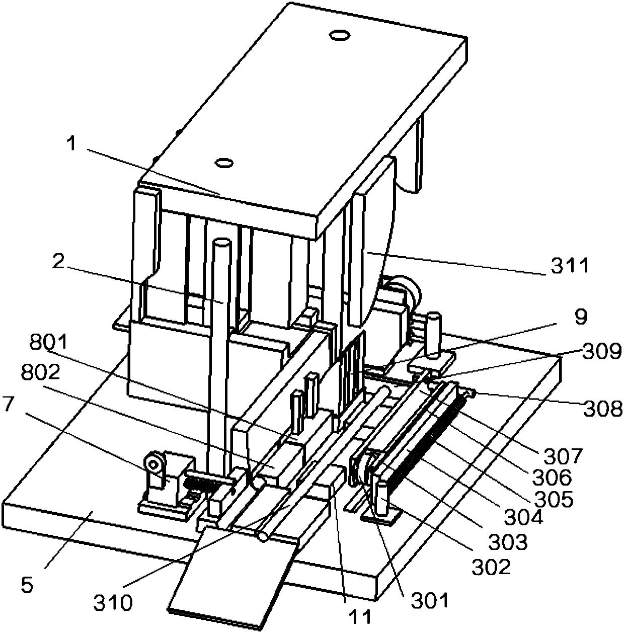
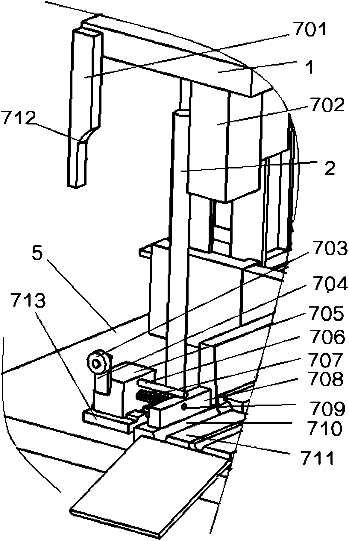
The invention provides a new feeding device for a high-efficiency louver forming mold, which includes a fixing seat and a collecting rack placed on it. A through groove is opened on the side wall of the fixing seat near the end of the collecting rack. The plate is placed in the through groove and is slidably connected with it, and the feed plate is driven to slide in the through groove through a sliding mechanism. The end of the fixed seat far away from the feed plate is provided with a buffer seat, and the buffer The seat is placed between the lower mold base and the upper template. A new type of feeding device for a high-efficiency louver forming die described in the present invention realizes the transformation of the vertical stamping force into a horizontal semi-finished product feeding movement through a simple structure, and changes the previous design idea of ​​the progressive die. The structure is simple and stable. High precision and high feeding accuracy, improve the effect of stamping and forming.

Description

technical field [0001] The invention belongs to the field of stamping dies, and in particular relates to a novel feeding device for a high-efficiency louver forming die. Background technique [0002] Stamping die is the main production method of hardware forming. According to the production and processing requirements of different hardware parts, different forms are designed to achieve the purpose. The commonly used dies are divided into progressive dies, compound dies and single dies. The main working forms Roughly the same, design the layout and the corresponding convex and concave molds according to different needs, and the other parts are traditional standard parts. Although it is easy to replace during use, it also limits the design ideas of the mold. For our common doors and windows. , the accuracy of stamping and rolling is not high, only good coordination is required. On the one hand, the form design of commonly used progressive dies and composite dies limits the des...

Claims


Application Information

Patent Timeline
Patent Type & Authority Applications(China)
IPC IPC(8): B21D37/08B21D35/00B21D45/04B21D43/08B21D43/00B21D37/12
CPCB21D37/08B21D35/002B21D37/12B21D43/003B21D43/08B21D45/04
Inventor 李连辉
Owner TIANJIN BOLIXIN HARDWARE PROD
Learn More