
Switch tube control method and device and inverter

A control method and a technology of a control device, which are applied to output power conversion devices, conversion of AC power input to DC power output, climate sustainability, etc., can solve problems such as stress exceeding the allowable value, reduce voltage stress, and improve opening and turn-off speed, reducing the effect of peak voltage

Inactive Publication Date: 2018-03-20
VERTIV CORP
View PDF4 Cites 1 Cited by
  • Summary
  • Abstract
  • Description
  • Claims
  • Application Information

AI Technical Summary

Problems solved by technology

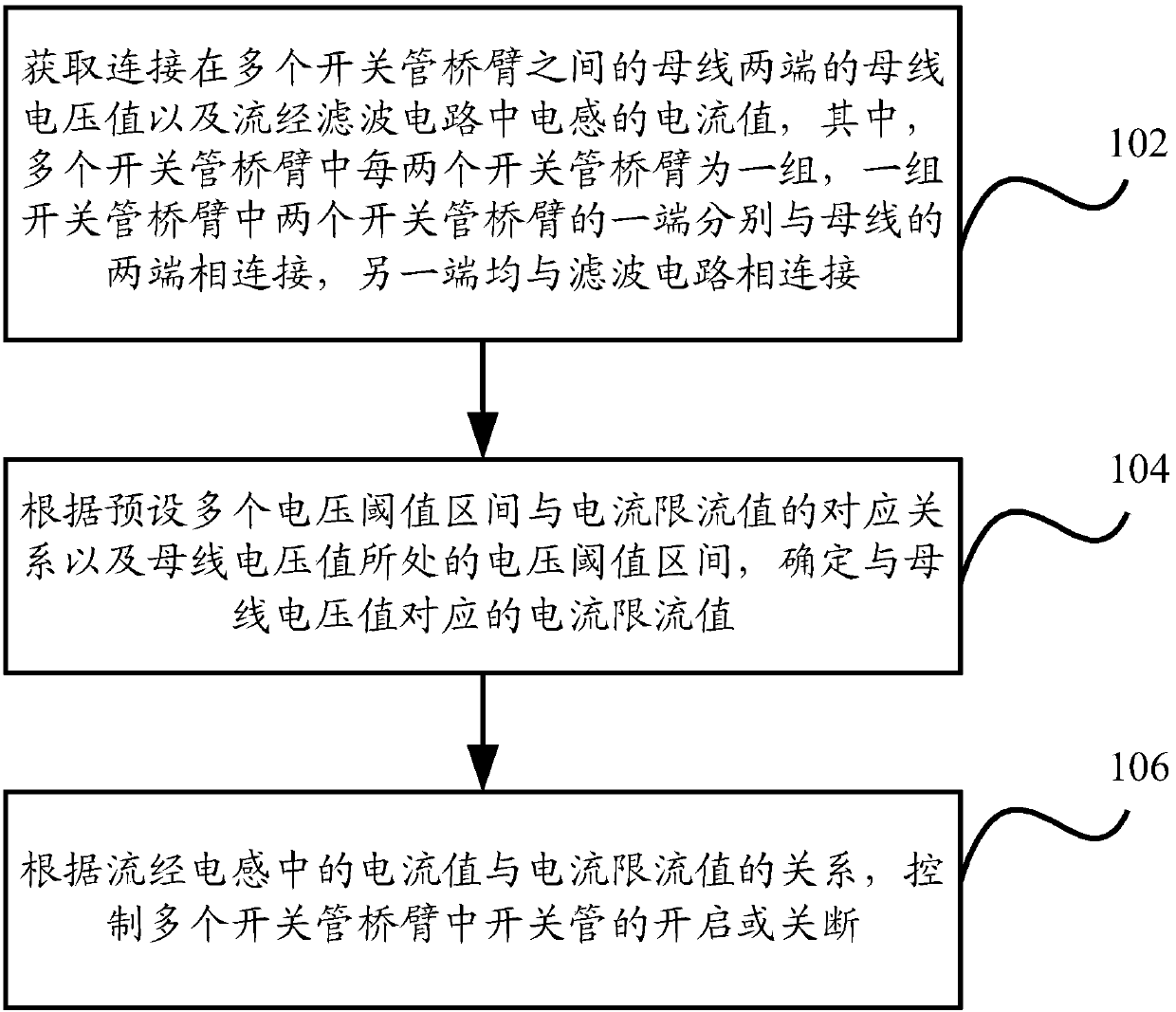
[0006] Embodiments of the present invention provide a switching tube control method, device, and inverter, which are used to solve the problem in the prior art that the voltage stress of the switching tube in the inverter exceeds the allowable value under severe working conditions, and improve the inverter's performance. Work reliability, can improve the switching tube turn-on and turn-off speed, reduce loss, improve system efficiency

Method used


Image

  • Switch tube control method and device and inverter
  • Switch tube control method and device and inverter
  • Switch tube control method and device and inverter

Examples


Embodiment Construction

[0019] Embodiments of the present application will be described below in conjunction with the accompanying drawings. It should be understood that the embodiments described here are only used to illustrate and explain the present application, and are not intended to limit the present application.

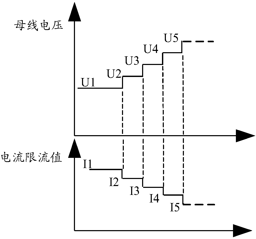
[0020] Aiming at the problem of increasing the loss of the switching tube and greatly reducing the system efficiency and reliability by slowing down the switching speed of the switching tube and reducing the voltage stress of the switching tube of the inverter under the harsh working conditions in the prior art, the present invention implements The example provides a switching tube control scheme. In this scheme, the inverter current limit value is determined according to the voltage threshold range of the bus voltage. When the bus voltage is too high, the current limit value is reduced to reduce the inverter current limit. The output current of the inverter is used to reduce the peak...


PUM


Abstract

An embodiment of the invention discloses a switch tube control method and device and an inverter that can help solve a problem that voltage stress of a switch tube in the inverter exceeds a permit value in adverse working conditions based on conventional technologies; work reliability of the inverter can be improved, switch-on and switch-off speed of the switch tube can be improved, loss can be reduced, and system efficiency can be increased. The switch tube control method comprises the following steps: a bus voltage value across two ends of a bus connected among a plurality of switch tube bridge arms and a current value of a current flowing through an inductor in a filter circuit are obtained; a current limit value corresponding to the bus voltage value is determined according to a presetcorrespondence relation between a plurality of voltage threshold value sections and current limit values and a voltage threshold value section in which the bus voltage value is positioned; switch tubes in the plurality of switch tube bridge arms are controlled to be switched on or off according to a relation between the current value of the current flowing through the inductor and the current limit value.

Description

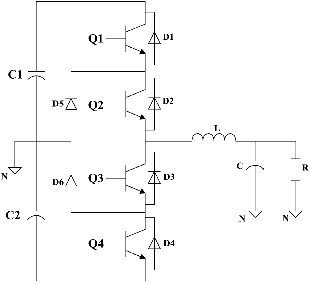
technical field [0001] The present invention relates to the technical field of communication power supplies, in particular to a switch tube control method and device used in an inverter circuit and an inverter using the switch tube control device. Background technique [0002] The inverter is a device that converts direct current into alternating current (DC / AC). The conversion circuit of the inverter is usually composed of a bus capacitor, an inverter bridge, an output filter circuit, a controller, etc. The inverter bridge is usually composed of multiple Each switching tube bridge arm is composed of two or more switching tubes, which is the core device of the inverter. [0003] In order to ensure the reliability of the inverter, it is necessary to ensure that the switch tube of the inverter is not damaged under various working conditions. Therefore, in order to avoid excessive current flowing through the switch tube and damage the switch tube, it is necessary to ensure The...

Claims


Application Information

Patent Timeline
Patent Type & Authority Applications(China)
IPC IPC(8): H02M1/08H02M7/537
CPCH02M1/08H02M7/537H02M1/0054Y02B70/10
Inventor 陈鹏周进伟王哲修彭向标
Owner VERTIV CORP
Learn More