Pipefitting for connecting metal compound tubular product

A metal composite pipe and metal insert technology, applied in the direction of pipe/pipe joint/pipe fitting, pipe element, pipe connection arrangement, etc., can solve the problem of leakage at the joint between plastic and metal, prevent air trapping and ensure sealing performance , the effect of low cost

Pending Publication Date: 2018-03-20
RIFENG ENTERPRISE FOSHAN CO LTD +2
View PDF14 Cites 5 Cited by
  • Summary
  • Abstract
  • Description
  • Claims
  • Application Information

AI Technical Summary

Problems solved by technology

[0007] The purpose of the present invention is to overcome the deficiencies of the prior art, and provide a pipe fitting for connecting metal composite pipes with low cost, excellent sealing performance, which can effectively solve the problems of trapped air, difficult insertion, leakage at the junction of plastic and metal, etc.

Method used


Image

  • Pipefitting for connecting metal compound tubular product
  • Pipefitting for connecting metal compound tubular product
  • Pipefitting for connecting metal compound tubular product

Examples


Embodiment 1

[0047] like Figure 1-2 As shown, the pipe fitting 10 used to connect the metal composite pipe 20 includes a plastic pipe fitting body 1, both ends of the plastic pipe fitting body 1 are socket hot-melt connection ends 11, and the socket hot-melt connection end 11 includes two layers in the radial direction , are respectively the outer layer tube 111 and the inner layer tube 112, the length of the outer layer tube 111 is greater than the length of the inner layer tube 112, the diameter of the outer layer tube 111 is greater than the diameter of the inner layer tube 112,

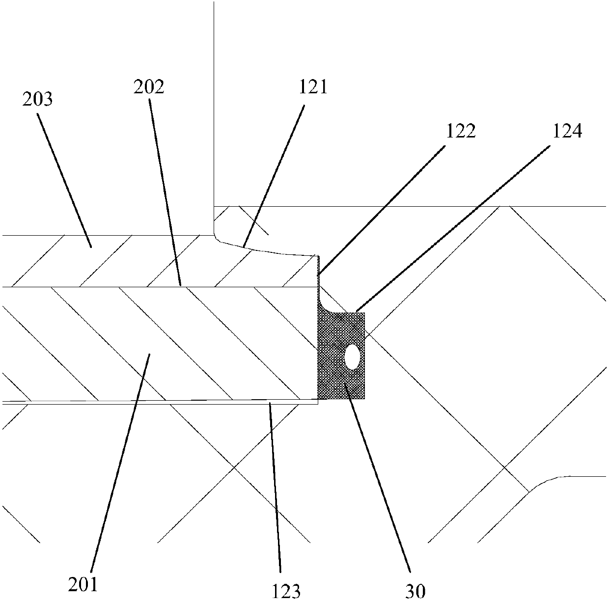
[0048] A socket 12 is formed between the outer tube 111 and the inner tube 112. The socket 12 includes a first sealing surface 121, a second sealing surface 122 and a third sealing surface 123. The first sealing surface 121 is used for compounding with metal The plastic inner layer 201 of the pipe 20 is hot-melt connected, the second sealing surface 122 is in contact with the metal middle layer 202 of the met...

Embodiment 2

[0065] like Figure 3-4 As shown, the pipe fitting 10 is a right-angle two-way connection, one end of which is a socket hot-melt connection end 11, and the other end is integrally injection-molded with the metal insert 2, and the center of the metal insert 2 is provided with a through hole 13 communicating with the plastic pipe fitting body 1. The threaded hole 21. The socket hot-melt connection end 11 is used for connecting with the metal composite pipe 20, and the end with the metal insert 2 is used for connecting with the faucet.

[0066] like Figure 5 As shown, the cross section of the storage tank 124 is rectangular, including a first axial surface 124a, a second axial surface 124b and a first radial surface 124c, the first axial surface 124a is connected with the second sealing surface 122, the second The two axial surfaces 124b are connected to the third sealing surface 123, and the first radial surface 124c is connected to the first axial surface 124a and the second...


PUM


Abstract

The invention discloses a pipefitting for connecting a metal compound tubular product. The pipefitting comprises a plastic pipefitting body. At least one end of the plastic pipefitting body is a socket hot melting connecting end; the socket hot melting connecting end comprises two layers radially: separately an outer layer pipe and an inner layer pipe; the length of the outer layer pipe is greaterthan the length of the inner layer pipe; the diameter of the outer layer pipe is greater than the diameter of the inner layer pipe; a socketing portion is formed between the outer layer pipe and theinner layer pipe; the socketing portion comprises a first sealing surface, a second sealing surface and a third sealing surface; the first sealing surface is used for being in hot melting connection to a plastic inner layer of the metal compound tubular product, the second sealing surface is in hermetically contact with a metal middle layer of the metal compound tubular product, and the third sealing surface is used for being in hot melting connection to a plastic outer layer of the metal compound tubular product; and a material storage tank is also arranged in the bottom of the socketing portion. The pipefitting disclosed by the invention is low in cost and excellent in sealing property and can solve the problems of air trapping, leakage at the connection of the plastic and the metal andthe like effectively.

Description

technical field [0001] The invention relates to the technical field of pipeline systems, in particular to a pipe fitting for connecting metal composite pipes. Background technique [0002] The existing connection methods of metal-plastic composite pipes usually include locking connection of metal pipe fittings and hot-melt connection of inner and outer layers of plastic pipe fittings. [0003] Among them, the connection cost of metal pipe fittings is high, and the operation is relatively complicated. [0004] The connection efficiency of the inner and outer heat-melt connection of plastic pipe fittings is more time-consuming and push-in resistance than the connection of single-layer pipes. The plastic pipe fittings are further divided into two ends that are socket hot-melt connection ends, one end that is a socket hot-melt connection end, and the other end that is a threaded connection end. [0005] Among them, problems such as trapped air and difficult insertion usually o...

Claims


Application Information

Patent Timeline
Patent Type & Authority Applications(China)
IPC IPC(8): F16L47/02F16L43/00F16L43/02
CPCF16L43/00F16L43/02F16L47/02
Inventor 林细勇邹伟彬王宏通赖化明周龙飞刁振彬邱帮龙何旺枝
Owner RIFENG ENTERPRISE FOSHAN CO LTD
Why Eureka
Try Eureka