
Method for cleaning injectors of a direct-injection controlled-ignition engine

An engine, jet-type technology, applied in the direction of cleaning methods using liquids, testing of engines, cleaning methods and appliances, etc., can solve problems such as pollution, deterioration, torque loss, etc.

Active Publication Date: 2018-03-16
VTESCO TECH GMBH
View PDF6 Cites 5 Cited by
  • Summary
  • Abstract
  • Description
  • Claims
  • Application Information

AI Technical Summary

Problems solved by technology

However, this compensation comes with worsening pollution
Also, beyond a certain clogging rate, the required corrections cannot be made and this leads to a reduction in engine performance (excessive consumption, loss of torque) as perceived by the driver

Method used


Image

  • Method for cleaning injectors of a direct-injection controlled-ignition engine
  • Method for cleaning injectors of a direct-injection controlled-ignition engine
  • Method for cleaning injectors of a direct-injection controlled-ignition engine

Examples


Embodiment Construction

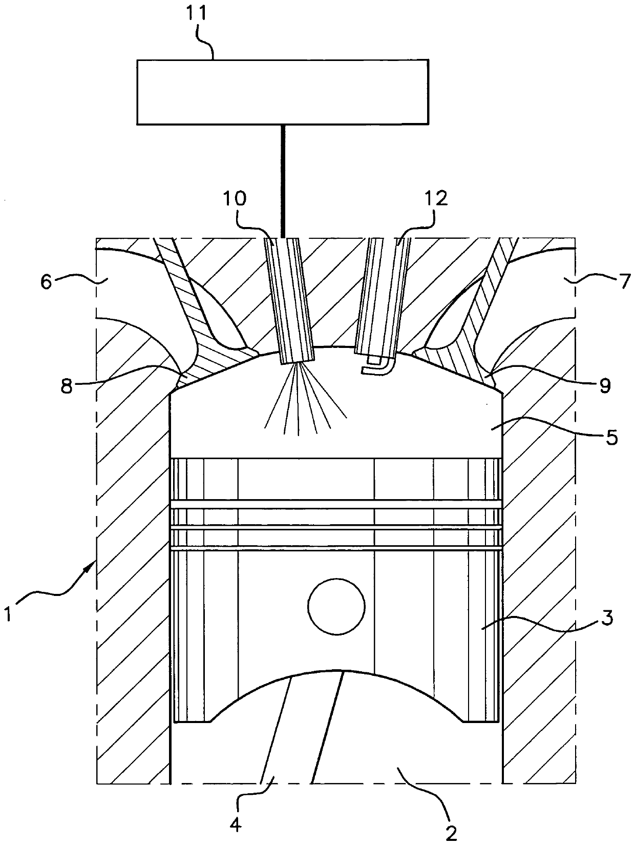
[0033] Such as figure 1 As shown, the method according to the invention aims at providing a method of cleaning the injectors of a direct injection controlled ignition engine 1 , which method may be preventive or remedial.

[0034] According to the figure 1 , a direct injection controlled ignition engine 1 is shown in the form of a single cylinder 2 housing a piston 3 actuating a connecting rod 4 and delimiting a combustion chamber 5 inside said cylinder.

[0035] This engine 1 also includes:

[0036] • inlet valve 8 on air inlet line 6,

[0037] • discharge valve 9 on discharge line 7,

[0038] • the injector 10, positioned to inject fuel directly into the combustion chamber 5, is controlled by the vehicle's engine control unit 11, programmed so as to determine the injection pressure PF and the injection time ti during each cycle,

[0039] • and spark plug 12 .

[0040] The object of the invention is to allow cleaning of the injectors 10 of the engine 1 as a preventive or...


PUM


Abstract

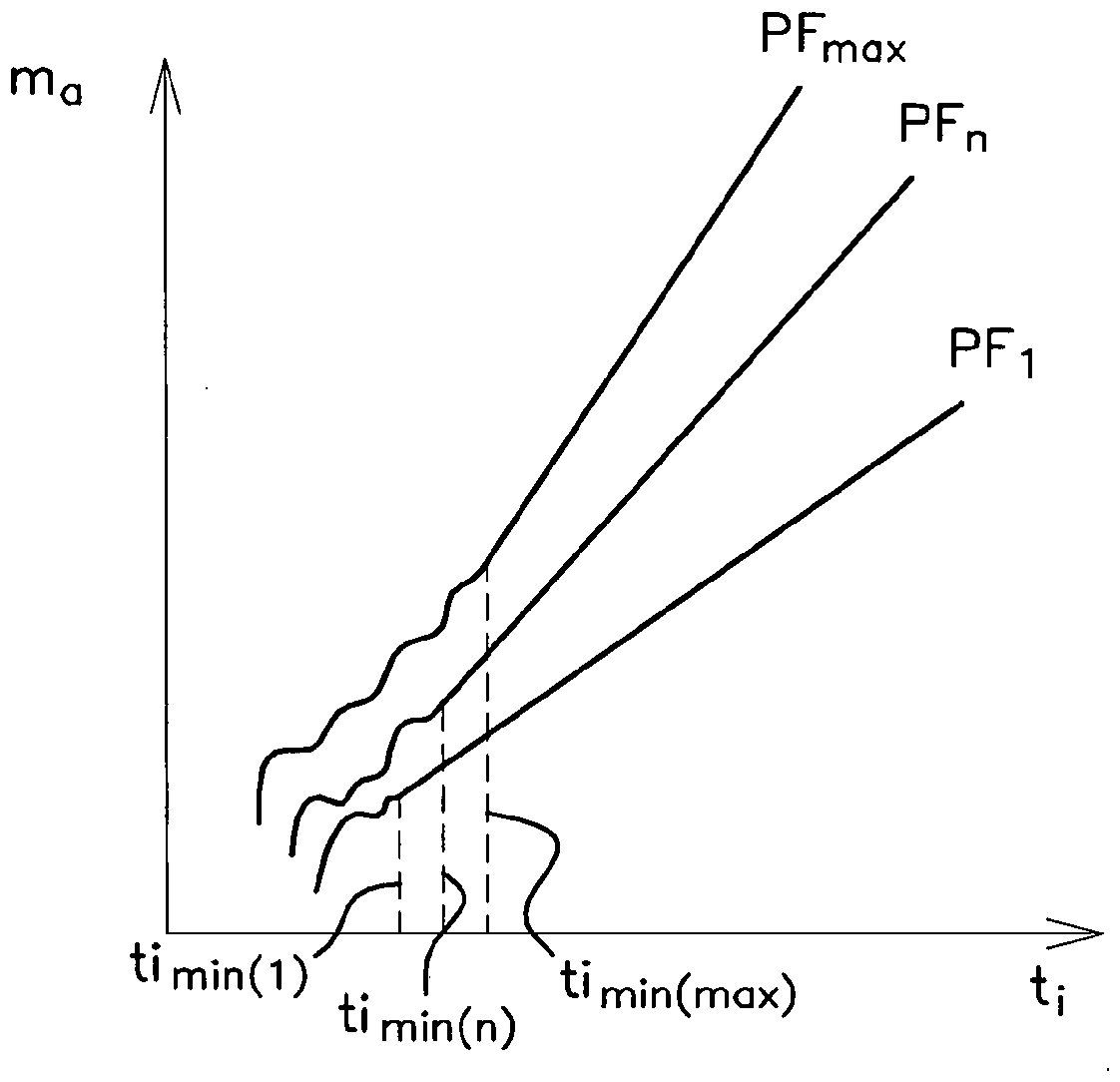
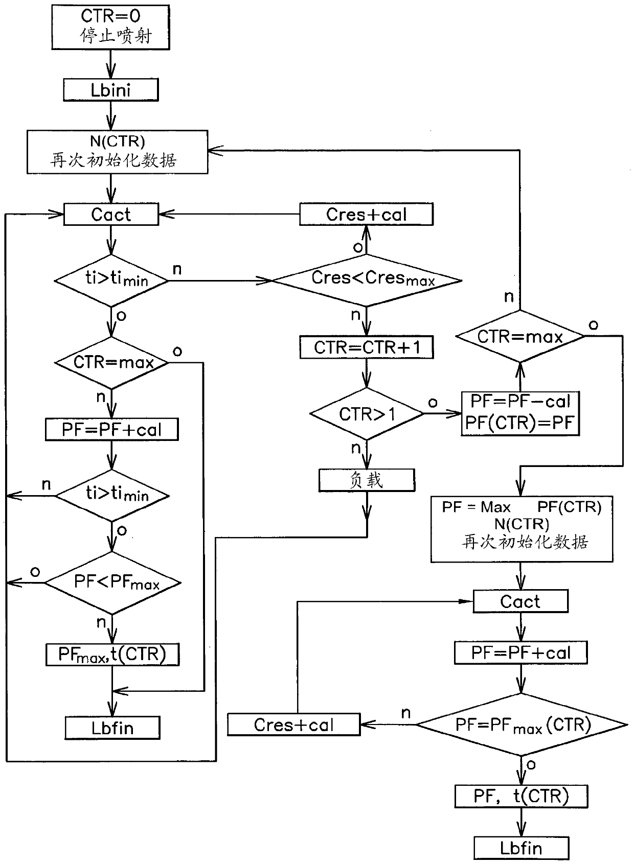
The invention relates to a method for cleaning injectors of a direct-injection controlled-ignition engine, whereby, when the said engine is operating at no load, the maximum fuel pressure at the injector is calculated first of all with a view to cleaning, by executing, for at least one predetermined engine operating speed, an iterative loop during each iteration of which the value of the pressureof the injected fuel is incremented by a predetermined value and the corresponding injection time at the said incremented pressure is determined so as to select, for each operating speed, a cleaning pressure equal either to the maximum fuel pressure that corresponds to an injection time longer than the calibrated minimum injection time determined for the said operating speed, or to a ceiling maximum pressure corresponding to a determined calibrated pressure for the engine / injectors system, if this calibrated pressure is reached while the iterative loop is being executed. Next, a cleaning treatment is applied that consists in selecting an operating speed that allows the maximum cleaning pressure, and in commanding the engine to operate with this speed applied and by programming the said cleaning pressure, for a treatment duration greater than the operating time permitted during running under such operating conditions.

Description

technical field [0001] The invention relates to a method for cleaning an injector of a direct injection controlled ignition engine. Background technique [0002] The injection holes of the injectors of direct-injection controlled-ignition engines often have reduced cross-sections of the fuel passages due to clogging of the injection holes, which is usually caused by the deposition of carbonaceous substances called soot . [0003] The effect of this clogging phenomenon is to reduce the amount of fuel actually injected relative to the amount calculated and controlled by the engine's central control unit (called Engine Control Unit or ECU). To mitigate this reduction, vehicles are equipped with a richness controller that operates on measurements provided by an oxygen probe, commonly referred to as a lambda probe, placed in the exhaust line and designed to increase injection Time to make the injected fuel quantity consistent with the fuel quantity calculated by ECU. However, ...

Claims


Application Information

Patent Timeline
Patent Type & Authority Applications(China)
IPC IPC(8): F02M65/00
CPCF02M65/008B08B3/02B08B9/0325F02D29/02F02D41/2467F02D2200/06F02D2200/1002F02D2200/101
Inventor J.迪莱翁J-L.弗雷莫P.塞雷基亚
Owner VTESCO TECH GMBH
Learn More