
Pneumatic crimping connector for electric engineering

A power engineering and crimping machine technology, applied in electrical components, circuits, connections, etc., can solve the problems of inconvenient portability, leakage, heavy weight, etc., to improve crimping stability and crimping efficiency, and ensure crimping. High quality and easy to carry

Pending Publication Date: 2018-03-16
湖州铭腾电力工程科技有限公司
View PDF0 Cites 4 Cited by
  • Summary
  • Abstract
  • Description
  • Claims
  • Application Information

AI Technical Summary

Problems solved by technology

The crimping machines used in current electric power engineering are usually hydraulic crimping machines, which are bulky and heavy, and are not convenient to carry and use. Moreover, it is found that the internal hydraulic oil often leaks due to overpressure during long-term use. Phenomenon, which seriously pollutes the environment and the crimping of wires. When the hydraulic crimping machine is crimping the wires, the applied pressure and crimping time of the crimping are judged based on human experience. big quality risk
[0003] To sum up, the existing hydraulic crimping machines used in electric power engineering still have great defects in structure and design, and cannot meet the needs of modern actual production

Method used


Image

  • Pneumatic crimping connector for electric engineering

Examples


Embodiment Construction

[0016] In order to make the technical problems, technical solutions and beneficial effects solved by the present invention clearer, the present invention will be further described in detail below in conjunction with the accompanying drawings and embodiments. It should be understood that the specific embodiments described here are only used to explain the present invention, not to limit the present invention.

[0017] In the description of the present invention, it should be understood that the terms "one side", "the other side", "both sides", "middle", "inside", "upper end", "lower end", "upper" The orientation or positional relationship indicated by , "lower", etc. is based on the orientation or positional relationship shown in the drawings, and is only for the convenience of describing the present invention and simplifying the description, rather than indicating or implying that the referred device or element must have a specific orientation , constructed and operated in a p...


PUM


Abstract

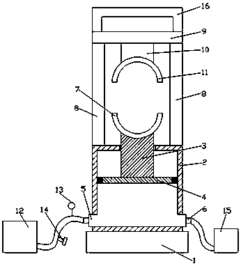
The invention relates to a pneumatic crimping connector for electric engineering. The machine is provided with a base. A cylinder room is fixedly arranged on the upper end of the base. A piston rod isvertically inserted into the upper end of the cylinder room. The lower end of the piston rod passes through the rear end of the cylinder room to be connected with a piston piece. The piston piece ishorizontally arranged in the cylinder room. An air inlet and an air outlet are respectively arranged on the two sides of the cylinder room below the piston piece. A semicircular movable pressing pieceis fixedly arranged on the upper end of the piston rod. Columns are fixedly arranged in positions which are on the upper end of the cylinder room and on the two sides of the semicircular movable pressing piece. A beam is horizontally and fixedly arranged on the upper ends of the columns. A connecting rod is arranged between the columns at the lower end of the beam. A semicircular fixed pressing piece is fixedly arranged at the lower end of the connecting rod and at the upper end of the semicircular movable pressing piece. The pneumatic crimping connector for electric engineering has a simplestructure. Wires are pneumatically crimped at fixed time and at fixed pressure. The overall crimping quality of wires is ensured. The weight of the whole device is reduced. The device is easy to carry. The crimping stability and the crimping efficiency of the crimping connector are improved.

Description

technical field [0001] The invention relates to the technical field of electric power engineering equipment, in particular to a pneumatic crimping machine for electric power engineering. Background technique [0002] With the continuous development of society, the power engineering industry has developed rapidly. In the power engineering industry, a variety of power equipment will be used, among which the crimping machine is an important part. The crimping machines used in current electric power engineering are usually hydraulic crimping machines, which are bulky and heavy, and are not convenient to carry and use. Moreover, it is found that the internal hydraulic oil often leaks due to overpressure during long-term use. Phenomenon, which seriously pollutes the environment and the crimping of wires. When the hydraulic crimping machine is crimping the wires, the applied pressure and crimping time of the crimping are judged based on human experience. Great quality hidden dang...

Claims


Application Information

Patent Timeline
Patent Type & Authority Applications(China)
IPC IPC(8): H01R43/048
CPCH01R43/048
Inventor 沈明良
Owner 湖州铭腾电力工程科技有限公司
Learn More