
Computer interlocking software development and realization system based on formalized model development

A technology for computer interlocking and system realization. It is applied in the directions of calculation, software testing/debugging, design optimization/simulation, etc. It can solve problems such as expensive cost, difficulty in simulation testing, and influence on verification of software design results.

Inactive Publication Date: 2018-03-16
CASCO SIGNAL
View PDF3 Cites 6 Cited by
  • Summary
  • Abstract
  • Description
  • Claims
  • Application Information

AI Technical Summary

Problems solved by technology

[0003] In addition, the development process of SIL4 software and the technical requirements used in software development are extremely demanding, few methods can meet the requirements of SIL4 software standards, and the final implementation also requires expensive costs as a price
The traditional code-based software development method has a large development workload and high difficulty, which prolongs the software development time
At the same time, it is difficult to realize the simulation test of the software in the general application layer for the software implemented by coding, which affects the verification of the software design results

Method used


Image

  • Computer interlocking software development and realization system based on formalized model development
  • Computer interlocking software development and realization system based on formalized model development
  • Computer interlocking software development and realization system based on formalized model development

Examples


Embodiment Construction

[0030] The present invention will be described in detail below in conjunction with the accompanying drawings and specific embodiments. This embodiment is carried out on the premise of the technical solution of the present invention, and detailed implementation and specific operation process are given, but the protection scope of the present invention is not limited to the following embodiments.

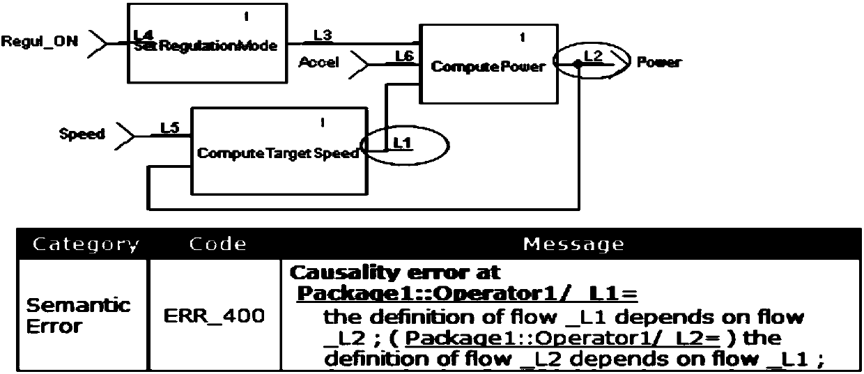
[0031] During the entire life development cycle of the interlocking system, the TOP-DOWN design method is used to decompose the requirements and allocation step by step. The decomposed hardware requirements are realized by independent secure hardware platforms. For software requirements, according to the development requirements of EN50128, a complete architecture design for the interlocking software is carried out. According to the design method of formalizing the logic part and refining the data part, the interlocking software is modeled using SCADE tools to realize the modeling of...


PUM


Abstract

The invention relates to a computer interlocking software development and realization system based on formalized model development. The system includes: an interlocking software logic module, which isused for realizing interlocking logic processing functions of the system, wherein modeling and designing of the interlocking logic functions are carried out by adopting an SCADE (safety-critical application development environment) tool; an interlocking software application interface module, which provides information transmission channels of logical operations and external interfaces, and is used for realizing parsing and packaging of various types of communication message data of the external interfaces, and completing information exchange with the interlocking software logic module at thesame time; and a testing module, which is used for carrying out simulation testing and safety verification on model logic designs. Compared with the prior art, a model of the invention has the advantages such as the advantages that C-language code which is suitable for use in an embedded operating system can be verified or automatically generated, and the generated code meets a series of safety features.

Description

technical field [0001] The invention relates to a computer interlocking software development and realization system, in particular to a computer interlocking software development and realization system developed based on a formalized model. Background technique [0002] The rapid development of high-speed railways and urban rail transit has brought convenience to people's travel, all thanks to the safety guarantee of railway signaling systems. As the core control system of the signaling system, the interlock system is a computer-based embedded real-time system that realizes interlock control of station equipment and ensures traffic safety. Computer interlocking system software is a typical safety-related software, which has very complex interlocking control logic and safety requirements centered on failure. The realization of its safety requirements is a very difficult task. In the design and development process of the interlocking system, ensuring the safety and reliabilit...

Claims


Application Information

Patent Timeline
Patent Type & Authority Applications(China)
IPC IPC(8): G06F17/50G06F11/36
CPCG06F11/3688G06F30/20
Inventor 王燕芩徐军强朱迎春马雯
Owner CASCO SIGNAL
Learn More