
Laser detector of laser casting instrument

A technology of laser detectors and wire casters, which is applied in the field of laser detectors, can solve the problems of low precision and troublesome operation, and achieve the effect of high positioning precision and easy operation

Inactive Publication Date: 2018-03-16
SUZHOU YIDI ELECTRONICS TECH
View PDF0 Cites 1 Cited by
  • Summary
  • Abstract
  • Description
  • Claims
  • Application Information

AI Technical Summary

Problems solved by technology

In specific use, it requires laser detectors to be used together to realize the positioning of the horizontal and vertical planes. The existing laser detectors cannot simultaneously complete the positioning of the horizontal laser line and the vertical laser line. The operator first completes the positioning of the horizontal and vertical planes. The positioning of the laser line, and then manually rotate the laser detector 90 degrees to position the vertical laser line, due to the manual operation, the operation is more troublesome and the accuracy is lower

Method used

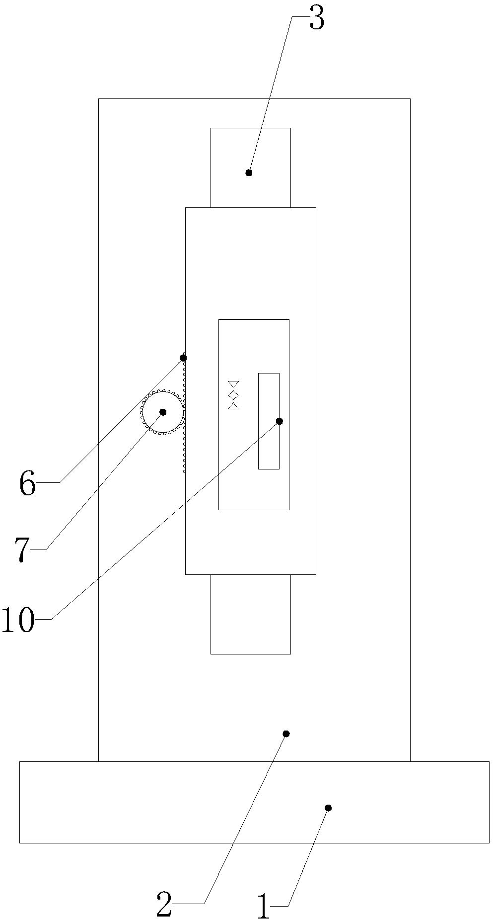
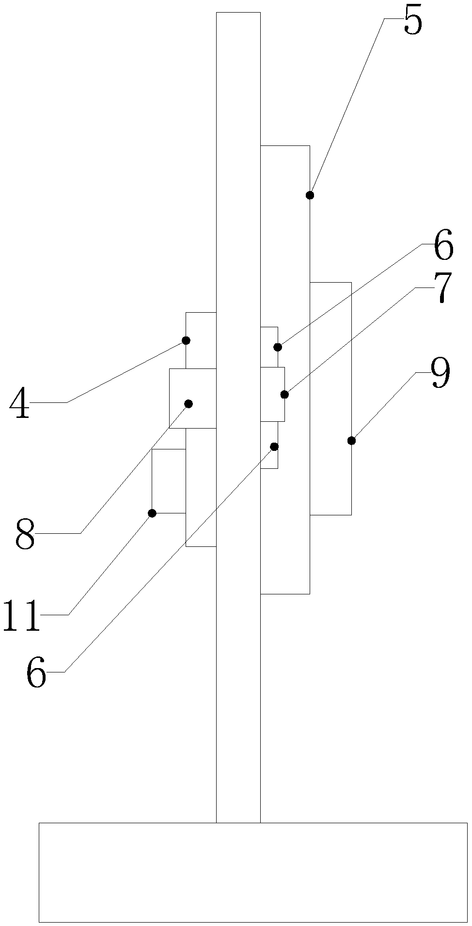
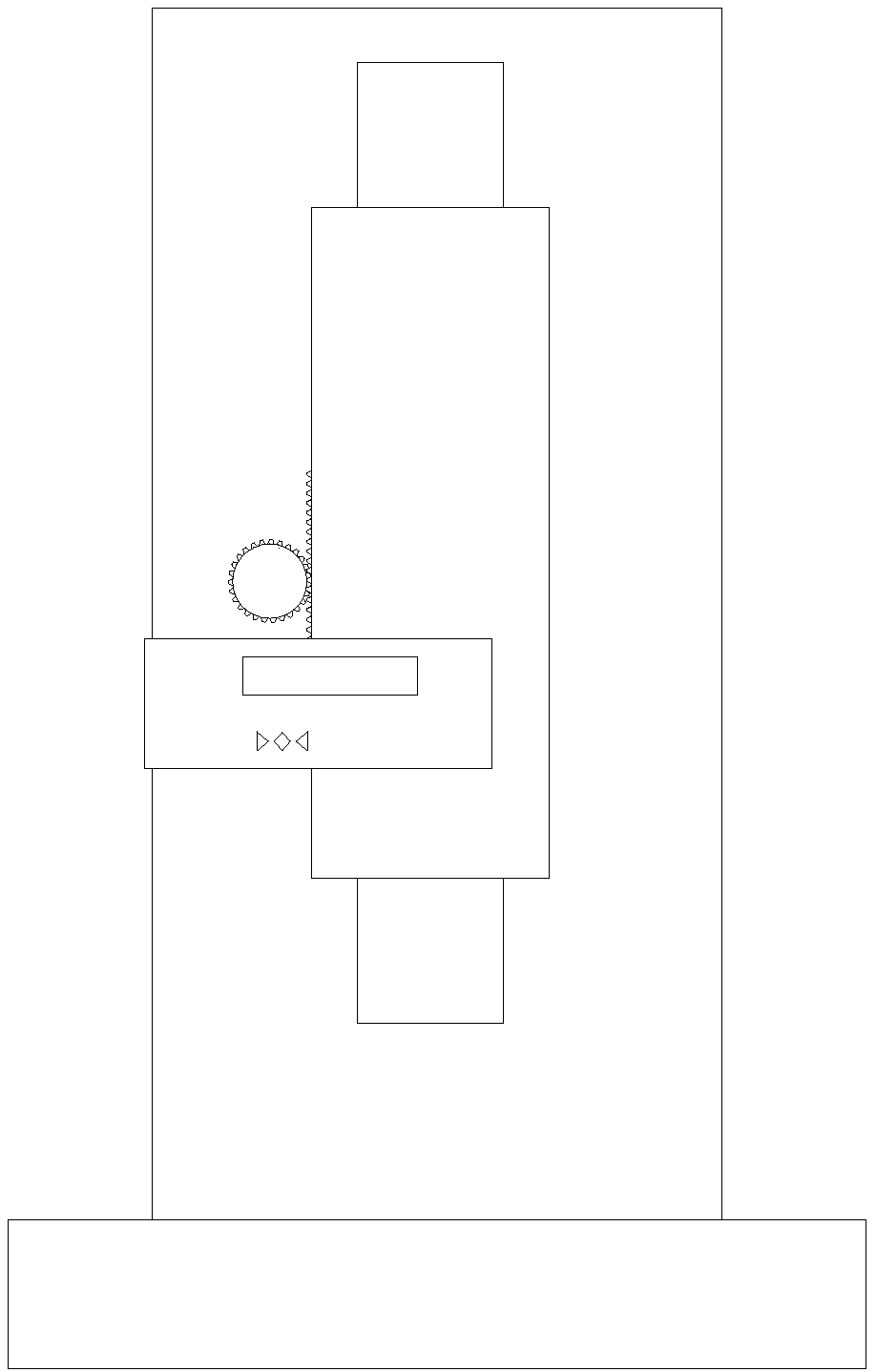

Image

  • Laser detector of laser casting instrument
  • Laser detector of laser casting instrument
  • Laser detector of laser casting instrument

Examples


Embodiment Construction

[0017] The specific implementation manners of the present invention will be further described in detail below in conjunction with the accompanying drawings and embodiments. The following examples are used to illustrate the present invention, but are not intended to limit the scope of the present invention.

[0018] see Figure 1 to Figure 3 , a laser detector for a line throwing instrument in a preferred embodiment of the present invention includes a base 1, a support plate 2 is provided on the surface of the base, and a slide penetrating through the support plate along the thickness direction of the support plate is provided on the front side of the support plate. Groove 3, the slide block 4 that slides with the chute is provided in the chute, the slide block is connected with the mounting plate 5, the mounting plate is located at the front side of the support plate, the left side of the mounting plate is provided with a toothed belt 6, and the mounting plate The left side o...


PUM


Abstract

The invention relates to a laser detector for a wire casting instrument, which comprises a base, a support plate is arranged on the surface of the base, a chute is arranged on the front side of the support plate, a slider is arranged in the chute, and a There is a toothed belt, the left side of the mounting plate is also provided with a pulley, the pulley is meshed with the toothed belt, and the rear side of the support plate is also provided with a first motor, the output shaft of the first motor passes through the support plate and is connected with the pulley. The front side of the board is provided with a detector body, the detector body includes a housing, the surface of the housing is provided with an incident window, and a laser receiving unit is arranged inside the housing, the laser receiving unit is a silicon photocell, and the laser receiving unit is located at the back of the incident window , the rear side of the slider is also provided with a second motor, the body of the second motor is fixedly arranged on the rear side of the slider, and the output shaft of the second motor passes through the slider, the mounting plate and is connected with the housing in turn. The laser detector of the line throwing instrument of the invention is easy to operate and has high measurement accuracy.

Description

technical field [0001] The invention relates to a laser detector, in particular to a laser detector for a line thrower. Background technique [0002] The line projector or ink line meter generally refers to a visible laser that can emit vertical or horizontal lines, and is used to mark horizontal or vertical lines on the target surface, and is widely used in decoration and construction. In specific use, it requires laser detectors to be used together to realize the positioning of the horizontal and vertical planes. The existing laser detectors cannot simultaneously complete the positioning of the horizontal laser line and the vertical laser line. The operator first completes the positioning of the horizontal and vertical planes. The positioning of the laser line, and then manually rotate the laser detector 90 degrees and then position the vertical laser line, due to the manual operation, the operation is cumbersome and the accuracy is low. [0003] In view of the above-ment...

Claims


Application Information

Patent Timeline
IPC IPC(8): G01C15/00
CPCG01C15/006
Inventor 薛启昊
Owner SUZHOU YIDI ELECTRONICS TECH
Learn More