Cold and hot gas gathering and distributing structure capable of achieving indoor temperature control

A gas, hot and cold technology, applied in the field of hot and cold gas collection and distribution structure, can solve the problems of large indoor air flow, inconvenient maintenance, poor environmental protection, etc., and achieve the effects of wide application range, convenient clamping and low cost

Active Publication Date: 2018-03-16
ZHEJIANG XINGGUANGDIANKE SMART HOME TECH CO LTD
View PDF11 Cites 0 Cited by
  • Summary
  • Abstract
  • Description
  • Claims
  • Application Information

AI Technical Summary

Problems solved by technology

[0002] The existing indoor cooling and heating methods include air-conditioning air supply and electric floor heating with electric heating wires inside. However, the above-mentioned methods have problems such as large indoor air flow, high energy consumption, poor environmental protection, and inconvenient maintenance.

Method used


Image

  • Cold and hot gas gathering and distributing structure capable of achieving indoor temperature control
  • Cold and hot gas gathering and distributing structure capable of achieving indoor temperature control
  • Cold and hot gas gathering and distributing structure capable of achieving indoor temperature control

Examples


Embodiment 1

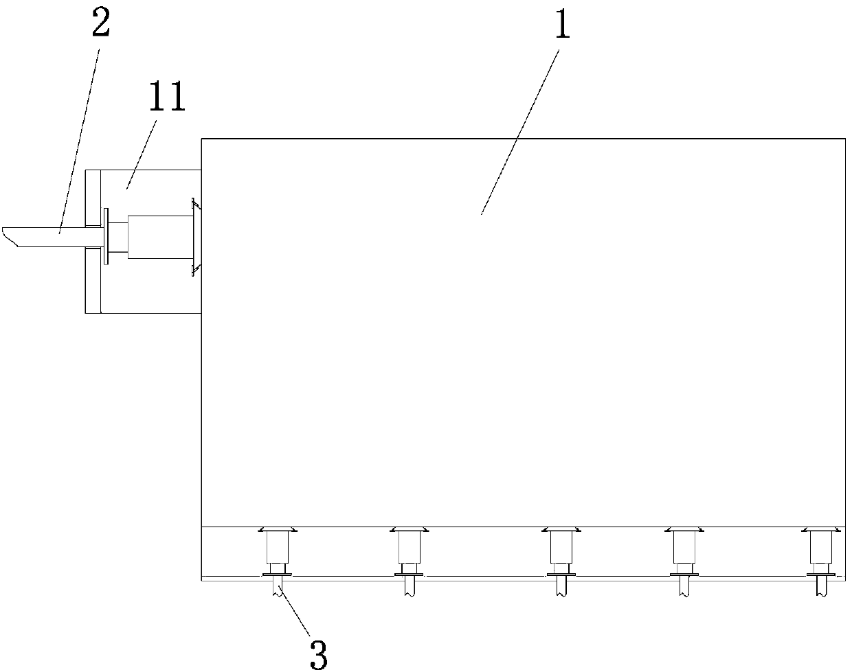
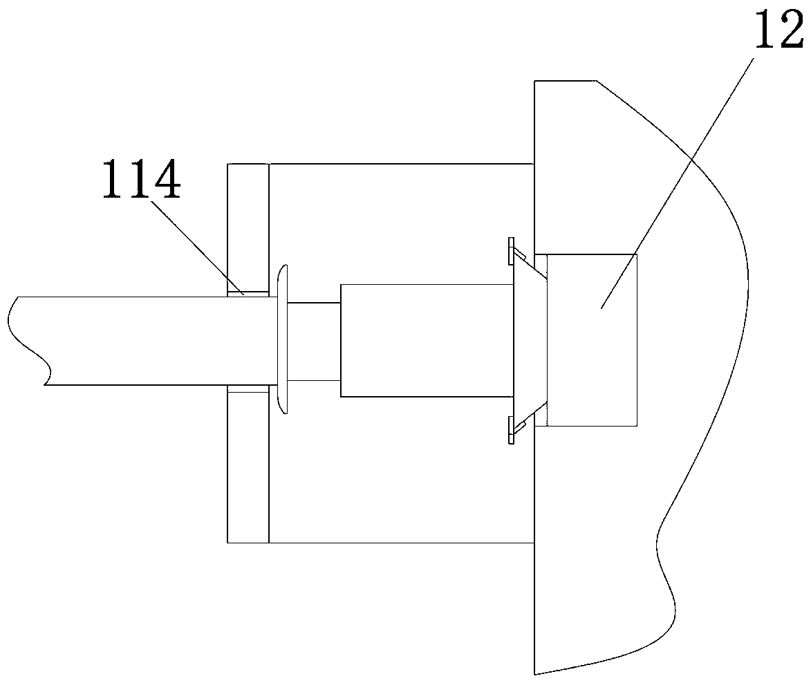
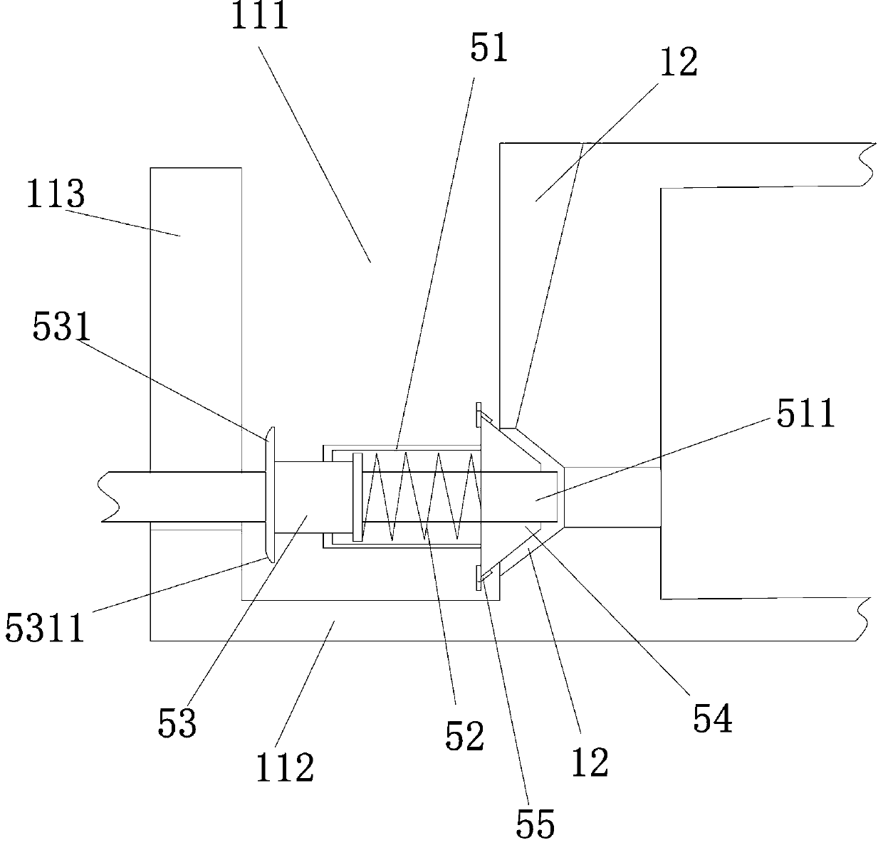
[0036] An indoor temperature-controlled hot and cold gas collection and distribution structure, characterized in that it includes a hollow square box body 1, the pipe end is connected with the box body and communicated with the box cavity and is the main air pipe 2 for supplying or returning air to the box cavity, connected On the box body wall adjacent to or opposite to the box body wall connected to the main trachea, the gas in the box cavity is delivered to the branch capillary 3, and the total trachea and the branch capillary tube are detachably connected to the On the box body, the box body is fixedly connected with a mounting slot 11 for connecting the main trachea or branch capillaries, and the mounting slot includes an upwardly open slot cavity 111, a slot bottom wall 112 and a slot The outer wall 113, the outer wall of the groove runs through the outer wall of the groove and is provided with an open-ended mounting socket 114, and the box body wall is provided with an a...


PUM


Abstract

The invention belongs to the fields of heating and refrigerating, and particularly relates to a cold and hot gas gathering and distributing structure capable of achieving indoor temperature control. The cold and hot gas gathering and distributing structure comprises a hollow square box body, a main gas pipe and branched thin pipes, wherein the pipe end of the main gas pipe is connected with the box body, the main gas pipe communicates with a box cavity and is used for supplying gas to the box cavity or returning gas, and the branched thin pipes are connected to the box body wall adjacent to oropposite to the box body wall, connected with the main gas pipe, of the box body and used for delivering gas in the box cavity out; and the main gas pipe and the branched thin pipes are detachably connected to the box body, erecting clamping slots used for enabling the main gas pipe or the branched thin pipes to be erected are fixedly connected to the exterior of the box body, each erecting clamping slot comprises a slot cavity with an upward opening, a slot bottom wall and a slot outer wall, an erecting embedded opening with the open upper end is formed in each slot outer wall in the mode ofpenetrating through the slot outer wall, and air holes communicating with the box cavity are formed in the portions, corresponding to the erecting embedded openings, of the box body walls. Accordingto the cold and hot gas gathering and distributing structure, the structure is simple, maintenance is convenient, parts can be reutilized, the cost is low, selective installation can be achieved, theinstalling position can be adjusted, the application range is wide, the practicability is high, and the cost is low.

Description

technical field [0001] The invention belongs to the field of heating and cooling, and in particular relates to an indoor temperature-controlled cold and hot gas collecting and distributing structure. Background technique [0002] The existing indoor cooling and heating methods include air-conditioning air supply and electric floor heating with electric heating wires inside. However, the above-mentioned methods have problems such as large indoor air flow, high energy consumption, poor environmental protection, and inconvenient maintenance. Contents of the invention [0003] The object of the present invention is to provide an indoor temperature-controlled cold and hot gas collecting and distributing structure to solve the above problems. [0004] Above-mentioned technical purpose of the present invention is achieved through the following technical solutions: [0005] An indoor temperature-controlled cold and hot gas collection and distribution structure, including a hollow...

Claims


Application Information

Patent Timeline
Patent Type & Authority Applications(China)
IPC IPC(8): F24F5/00F24F13/02F16L41/03
CPCF16L41/03F24F5/00F24F13/02
Inventor 何家忠杨杰
Owner ZHEJIANG XINGGUANGDIANKE SMART HOME TECH CO LTD
Why Eureka
Try Eureka