Refrigerating and heating vacuum pipeline structure

A vacuum pipeline, refrigeration and heating technology, applied in heating methods, pipeline layout, household heating, etc., can solve the problems of large indoor air flow, poor environmental protection, inconvenient maintenance, etc., to improve heat dissipation efficiency, not easily twisted or damaged, and ensure The effect of stability

Pending Publication Date: 2018-02-09
ZHEJIANG XINGGUANGDIANKE SMART HOME TECH CO LTD
View PDF6 Cites 0 Cited by
  • Summary
  • Abstract
  • Description
  • Claims
  • Application Information

AI Technical Summary

Problems solved by technology

[0002] The existing indoor cooling and heating methods include air-conditioning air supply and electric floor heating with electric heating wires inside. However, the above-mentioned methods have problems such as large indoor air flow, high energy consumption, poor environmental protection, and inconvenient maintenance.
[0003] Furthermore, in order to ensure that many factors that may cause deviation or slight distortion of the pipeline in the process of laying the pipeline, such as laying the pipeline and then laying the decorative cloth layer or balance layer or pouring cement, PVC, etc. can be used during installation. The material tube that bends itself during the process, the vacuum degree of this type of material tube is not a problem, but generally the heat preservation effect is better, and the heat dissipation is slow, so it is not suitable for the application that needs to quickly export the temperature inside the tube with special requirements

Method used


Image

  • Refrigerating and heating vacuum pipeline structure
  • Refrigerating and heating vacuum pipeline structure
  • Refrigerating and heating vacuum pipeline structure

Examples


Embodiment 1

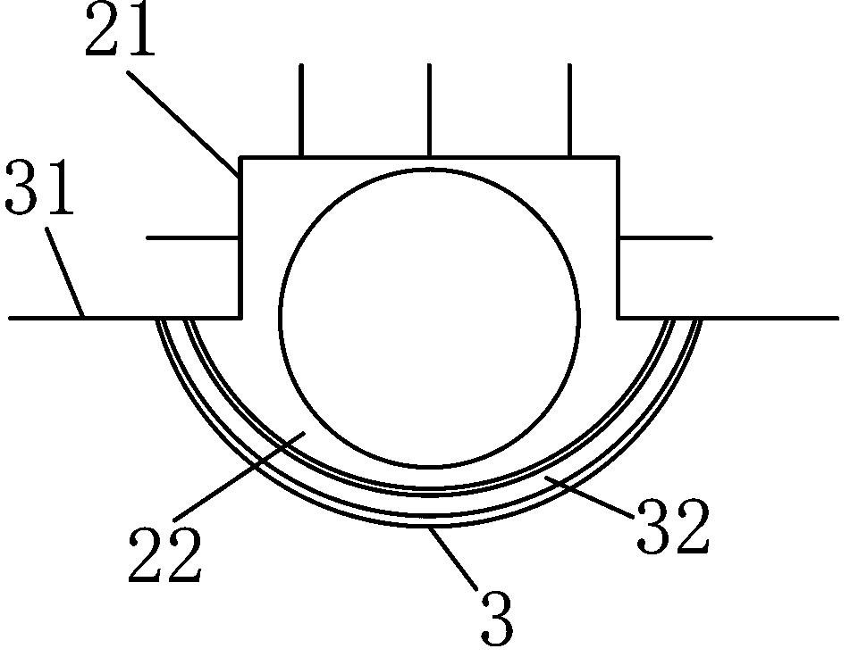
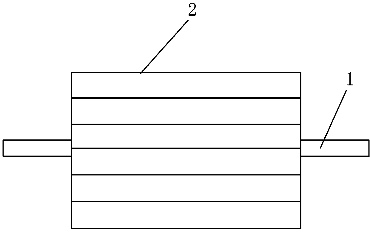
[0029] A vacuum pipeline structure for refrigeration and heating, including a pipe network system laid in the wallboard, floor or cement filling layer, and a main pipe 1 for supplying or returning air connecting the pipe network systems in each room. The pipe network system includes a plurality of vacuum network pipes 2 with circular pipes inside that are respectively connected to the main pipe at both ends. The lower part or the arc-shaped deflection part 22 that is convenient to adjust the network pipe connected to the lower part, the center line of the deflection part and the axis line of the circular pipe are all located on the symmetrical center plane of the stable part; the bottom surface of the network pipe Covered with a plastic insulation board 3, the two sides of the insulation board extend upwards to the bottom of the stable part, and the sides of the insulation board continue to extend outwards to form insulation wings 31, and a sponge is also arranged between the i...

Embodiment 2

[0031] The difference from the above embodiment is that the upper and lower circles of the outer contour of the network pipe respectively form a stabilizing part and a deflecting part, and the two ends of the top of the deflecting part exceed the two side edges of the stabilizing part.

Embodiment 3

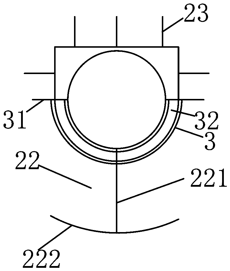
[0033] The difference from the above embodiment is that the bottom of the network pipe is connected with a deflection part; the deflection part includes a top connected to the network pipe, a bottom extending downwards to form a vertical beam frame 221 arranged radially along the circular pipe, and a center of symmetry connected to the The arc slats 222 at the bottom of the vertical beam frame, the two sides of the arc slats are raised upward in an arc shape.


PUM


Abstract

The invention belongs to the field of heating and refrigeration, and particularly relates to a refrigerating and heating vacuum pipeline structure. The refrigerating and heating vacuum pipeline structure comprises a pipe network system laid in a wallboard, in the floor or in a cement filling layer, and a main pipe which is connected with the pipe network system of each indoor and is used for supplying air or returning air; and the pipe network system comprises a plurality of vacuum net pipes with two ends connected with the main pipe and internally provided with circular pipelines, wherein thenet pipes each comprise a stable part and an arc-shaped deflection part, the stable part is at least located at the upper part and is formed with a square outer contour and is used for stabilizing, the arc-shaped deflection part is arranged on the lower part or is connected to the lower part and is used for conveniently adjusting the net pipes, and circle centers of the net pipes are used as center positions of the deflection parts. According to the refrigerating and heating vacuum pipeline structure, the specific stable parts and the deflection parts are cooperated so that the steel net pipes can be stabilized, convenient and accurate in installation and capable of being stably and efficiently used for a long time and is prevented from being damaged easily.

Description

technical field [0001] The invention belongs to the field of heating and cooling, and in particular relates to a cooling and heating vacuum pipeline structure. Background technique [0002] The existing indoor cooling and heating methods include air-conditioning air supply and electric floor heating with electric heating wires inside. However, the above-mentioned methods have problems such as large indoor air flow, high energy consumption, poor environmental protection, and inconvenient maintenance. [0003] Furthermore, in order to ensure that many factors that may cause deviation or slight distortion of the pipeline in the process of laying the pipeline, such as laying the pipeline and then laying the decorative cloth layer or balance layer or pouring cement, PVC, etc. can be used during installation. For material tubes that are bent by themselves during the process, the vacuum degree of such material tubes is not a problem, but generally the heat preservation effect is go...

Claims


Application Information

Patent Timeline
Patent Type & Authority Applications(China)
IPC IPC(8): F24F5/00F24F13/02
CPCF24F5/0003F24F13/0227F24F13/0263F24F2221/17
Inventor 何家忠杨杰
Owner ZHEJIANG XINGGUANGDIANKE SMART HOME TECH CO LTD
Why Eureka
Try Eureka