Unequal rate radiation heat conductive device
A technology of radiant heat and speed, applied in the field of heat transfer, can solve the problems of high manufacturing cost, high power and energy, etc., achieve the effect of wide application range and reduce manufacturing cost
- Summary
- Abstract
- Description
- Claims
- Application Information
AI Technical Summary
Problems solved by technology
Method used
Image

Examples
Embodiment 1
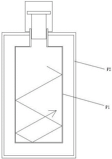
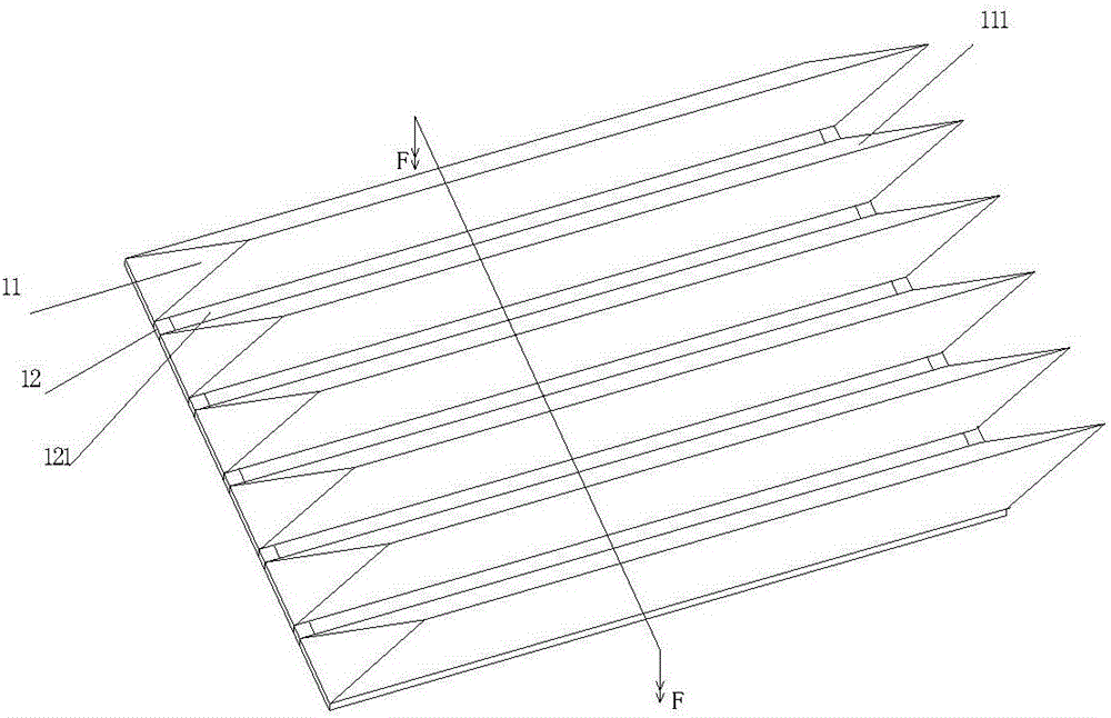
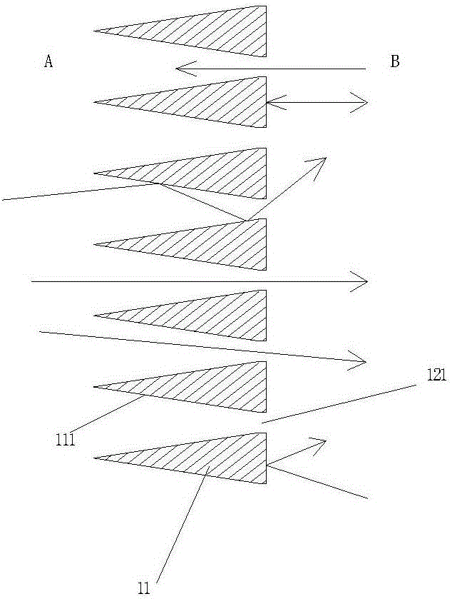
[0021] see figure 2 and 3 , the unequal rate radiation heat transfer device, including an inner cavity A and an outer cavity B, a barrier wall is provided between the inner cavity A and the outer cavity B, and the barrier wall is provided with a light-gathering wall 11 with a light-gathering function and a light-transmitting wall The light-transmitting wall 12, the cross-section of the light-gathering wall 11 is provided with a continuous steep wrinkled-shaped slope structure 111 with a light-gathering effect at intervals, and the cross-section of the light-transmitting wall 12 is a sheet structure; each slope structure 111 The slopes on both sides are located on the surface of the light-transmitting wall 12 of the barrier wall, and on the surface of the light-transmitting wall 12 of the barrier wall, light-transmitting holes 121 are correspondingly provided between the slopes of adjacent slope structures; the inner cavity A has a solid chamber of air ( Or a liquid space wit...
Embodiment 2
[0024] see Figure 4 , similar to Example 1. The unequal rate radiation heat transfer device includes an inner cavity A and an outer cavity B. A barrier wall is provided between the inner cavity A and the outer cavity. Wall 22, there is a distance P between the light-concentrating wall 21 and the light-transmitting wall 22, and each convex lens structure is used to guide light to the light-transmitting hole; Above, the cross-section of the concentrating wall 21 is a continuous convex lens structure 211 with a concentrating effect (both sides of the convex lens structure 211 are convex, but the left side can also be convex, and the right side can be concave or flat), and the cross-section of the light-transmitting wall 22 It is a sheet-like structure, and the light-transmitting wall 22 is provided with light-transmitting holes 221 at intervals, and the convex lens structure 211 can guide light into and pass through the light-transmitting holes 221; the inner cavity A has an ai...
Embodiment 3
[0026] see Figure 5 , similar to Example 1 or 2. Compared with Embodiment 2, the difference is that the cross-section of the concentrating wall 31 is a continuous concave mirror structure 311 with a concentrating effect, and the concave surface of the concave mirror structure 311 faces the light-transmitting wall 32, and the concave surface of the concave mirror structure 311 is only a converging surface. Light between the light wall 31 and the light-transmitting wall 32 is introduced into the light-transmitting hole 321 .
[0027] The arrows drawn in the above-mentioned figures indicate the light radiation path.
[0028] When the unequal rate radiation heat transfer device described in the above embodiments is applied, it can be used as a core component to manufacture equipment that requires temperature difference effects, such as refrigeration (lower temperature in the inner cavity), heating (higher temperature in the outer cavity), dehumidification (The inner cavity will...
PUM
 Abstract
Description
Claims
Application Information
 - R&D
- Intellectual Property
- Life Sciences
- Materials
- Tech Scout
- Unparalleled Data Quality
- Higher Quality Content
- 60% Fewer Hallucinations
Browse by: Latest US Patents, China's latest patents, Technical Efficacy Thesaurus, Application Domain, Technology Topic, Popular Technical Reports.
© 2025 PatSnap. All rights reserved.Legal|Privacy policy|Modern Slavery Act Transparency Statement|Sitemap|About US| Contact US: help@patsnap.com