Inner unit for dehumidification machine

A technology for dehumidifiers and indoor units, applied in mechanical equipment, household heating, space heating and ventilation details, etc., can solve the problems of poor filtering effect, limited dehumidification power, poor mute effect, etc., to increase connection strength and dehumidification. The effect of uniform temperature control and good dehumidification effect

Pending Publication Date: 2019-01-18
ZHEJIANG XINGGUANGDIANKE SMART HOME TECH CO LTD
View PDF12 Cites 0 Cited by
  • Summary
  • Abstract
  • Description
  • Claims
  • Application Information

AI Technical Summary

Problems solved by technology

[0002] The existing indoor air environment control is generally controlled by air conditioners. Most air conditioners are equipped with dehumidification function, and some air conditioners are not equipped with dehumidification function. Some rooms are equipped with independent dehumidification equipment. The function of the existing dehumidification equipment is dehumidification. The principle is to use the condenser to dehumidify first, then heat the evaporator and send it out at room temperature. All the structures are compact in the all-in-one machine, and the dehumidification power is limited. In terms of the dehumidification area and actual efficacy, the equipment cost is relatively low. High, inconvenient to disassemble and maintain
Moreover, the integrated dehumidifier can be placed in any room, but the problem of drainage treatment is more troublesome. The dehumidification water needs to be treated frequently, and because the dehumidification effect is not good, so the accumulated water can be cached in the integrated machine.
Moreover, the existing air source, whether it is a dehumidifier or an air conditioner, is the indoor air at the edge of the nearby indoor unit, which is close to the air outlet, and the indoor circulation is slow.
[0003] The existing dehumidification equipment will be equipped with a fan with required power according to different dehumidification power requirements, but the fan workload is limited, the air volume is limited, and the space inside the dehumidifier is limited, which may cause the actual air flow of even a high-power fan to fail. Due to the design requirements of the pumping and supplying air, the existing dehumidifiers generally use a small-area independent body structure to apply one machine to each independent space, and now some fans pump and supply air speed mainly depends on the speed of the fan, that is, the indoor air The speed of circulation mainly depends on the speed of the fan. To speed up the internal circulation will inevitably increase the speed of the fan and increase the power.
Furthermore, the existing dehumidifiers have a simple pumping and blowing structure, poor mute effect, and are easily damaged, and will also take away part of the low-level wind that still contains moisture, reducing the dehumidification effect.
[0004] The existing dehumidification equipment adopts the traditional filter structure used in the air conditioner internal unit. Its filtering effect is limited, and it can only perform primary filtration but not fine, and the filter generally can only be disassembled and washed without replacement. Over time, the filtering effect will be worse, and it is not suitable for the finer filtering requirements of high power

Method used


Image

  • Inner unit for dehumidification machine
  • Inner unit for dehumidification machine
  • Inner unit for dehumidification machine

Examples


Embodiment 1

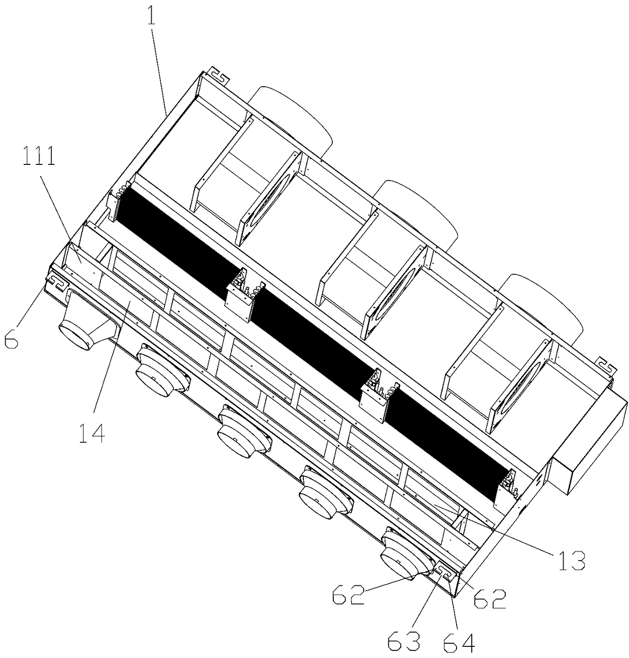
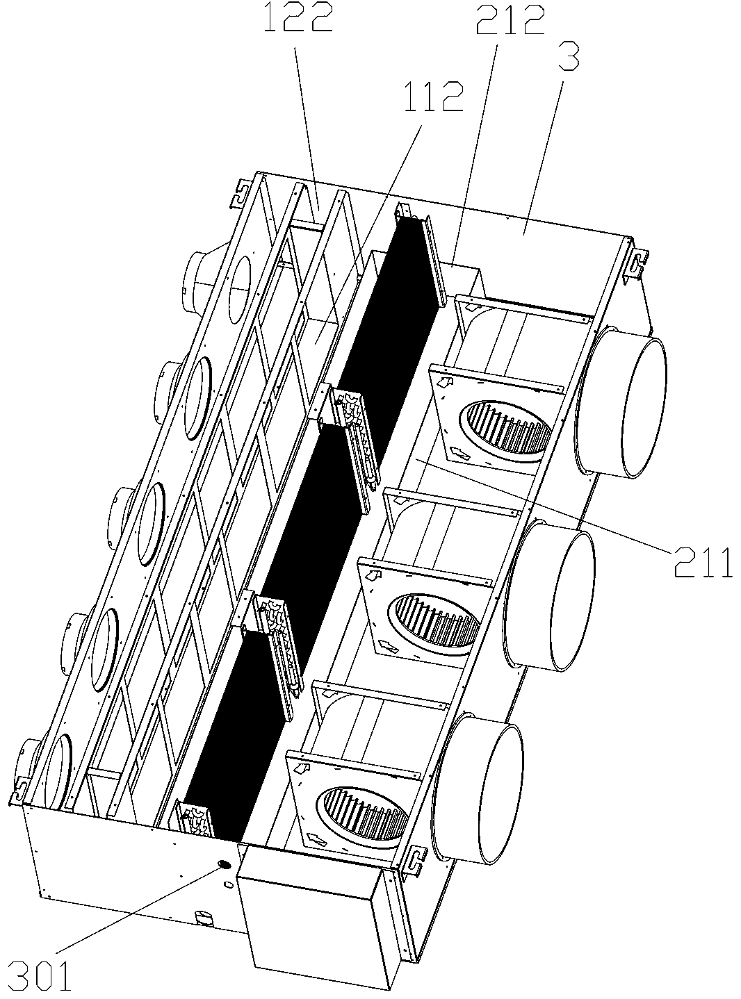
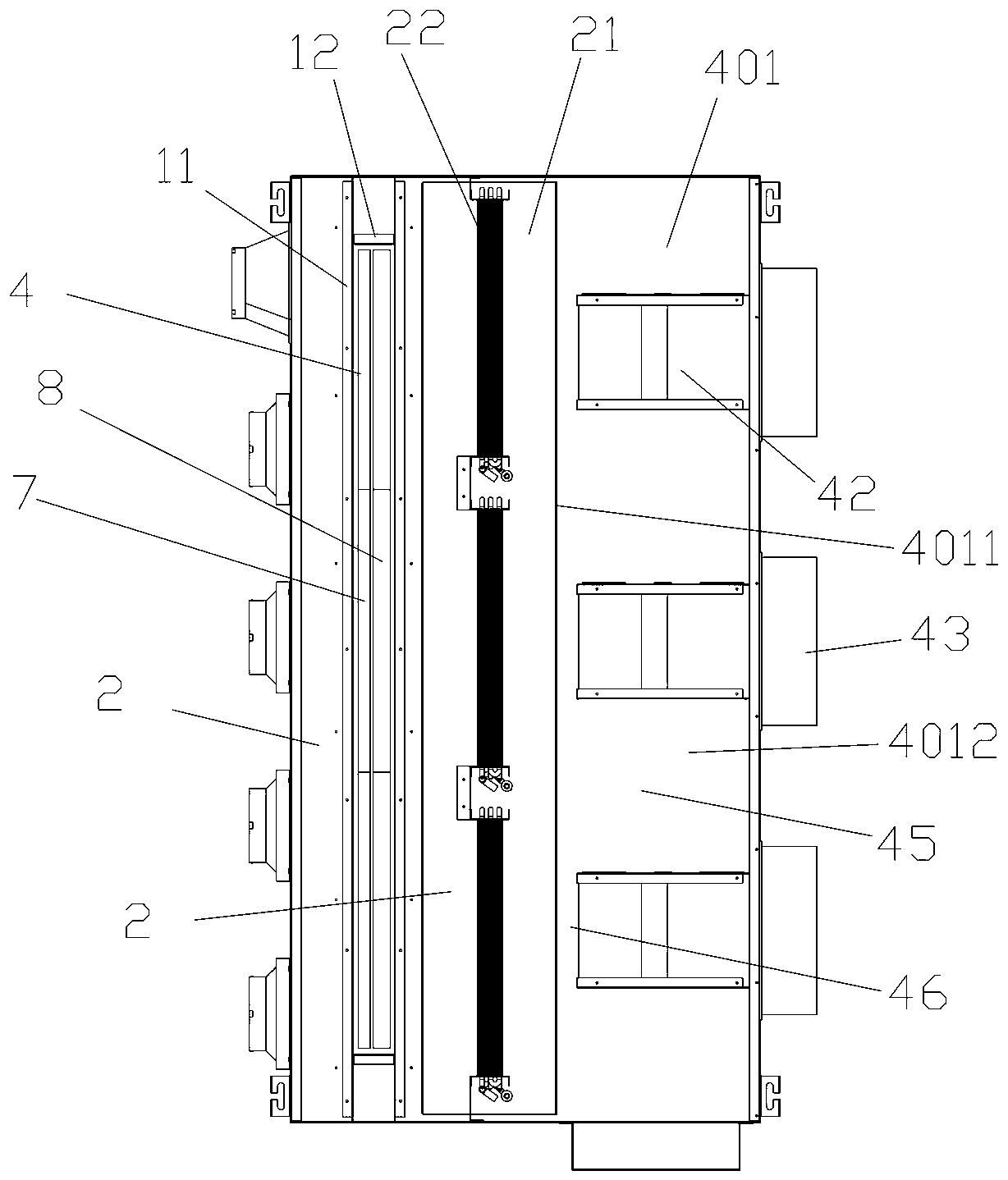
[0061]An inner unit of a dehumidifier, comprising a body shell 1 and a filter structure, a dehumidification structure, and an air blowing structure arranged in the body shell along the air flow direction from the air inlet to the air outlet; The body plate is connected to the body end plates 3 at both ends between the side body plates, the base plate at the bottom, and the top plate at the top; The air outlet body plate; the filter structure includes a filter core frame and a filter core 4 arranged in the filter frame, and the dehumidification structure includes a collection and drainage groove 21 and one or more edges arranged in the collection and drainage groove The heat exchanger 22 arranged in the longitudinal direction of the collection and drainage grooves, the air suction structure includes one or more air suction units 42 arranged side by side in sequence and connected to the outer surface of the air outlet body plate and together with the air suction unit. A correspo...

Embodiment 2

[0075] The difference from the above-mentioned embodiments is that the ventilation part includes at least two horizontal connecting rods 1121 arranged in parallel up and down and several vertical clamping rods 1122 connected between the frame connecting rods. The enclosure forms a transom window.

[0076] The vertical clamping bar is an arc-shaped clamping bar bar that is gradually concaved toward the inner part of the clamping groove cavity from the upper and lower ends to the middle. The curved design of the vertical clamping rod can improve the clamping degree of the filter element, the structure is more stable, and the noise is lower during use.

[0077] The outer upper, lower and both ends of the clamp frame are provided with a clamp frame solid edge 15 formed by turning outwards against the clamp groove cavity, and a number of holes for passing bolts are opened on the clamp frame solid edge. hole. The fixed edge of the clip frame can not only be used for the connection...

Embodiment 3

[0084] The difference from the above-mentioned embodiment is that the collection and drainage tank includes long tank walls 211 located on both sides and end tank walls 212 connected between the two long tank walls located at both ends, wherein the bottom of the end tank wall at one end has a hole The water outlet, the drain pipe structure is connected to the water outlet, the heat exchanger is connected to the water collection and drainage groove through the wind-proof connecting plates at both ends, and the two long groove walls are located at the outlet of the heat exchanger. The long groove wall on one side extends upward to form a speed-increasing baffle part 2111 for speeding up the wind, and the height of the speed-raising baffle part is higher than the long wall of the groove on the other side. The drain pipe adopts an anti-overflow drain pipe, and a section of water seal pipe that bends downwards can be set on the drain pipe, so that the water from the water outlet wil...


PUM


Abstract

The invention belongs to the field of regulation and control of indoor air environments, and particularly relates to an inner unit for a dehumidification machine. The inner unit comprises a machine body case, a filtering structure, a dehumidification structure and an air sucking and feeding structure, and the filtering structure, the dehumidification structure and the air sucking and feeding structure are sequentially arranged in the air flowing direction from inlet air to outlet air; the machine body case comprises side machine body plates located at the two sides, machine body end plates connected between the side machine body plates and located at the two ends, a bottom plate located at the bottom and a machine top plate located at the top; the side machine body plates comprise air inlet machine body plates provided with machine body air inlets and air outlet machine body plates provided with machine body air outlets. The inner unit is simple in structure, has the function of the dehumidification machine when it is hot, and can be used as a central air conditioner whether it is hot or cold. Compared with existing central air conditioners, the indoor unit is simpler in structureand lower in cost, indoor dehumidification and moisture control are quicker and evener than those of existing dehumidification and moisture control equipment, and the body feeling is more comfortable.

Description

technical field [0001] The invention belongs to the field of indoor air environment regulation, and in particular relates to an inner unit of a dehumidifier. Background technique [0002] The existing indoor air environment control is generally controlled by air conditioners. Most air conditioners are equipped with dehumidification function, and some air conditioners are not equipped with dehumidification function. Some rooms are equipped with independent dehumidification equipment. The function of the existing dehumidification equipment is dehumidification. The principle is to use the condenser to dehumidify first, then heat the evaporator and send it out at room temperature. All the structures are compact in the all-in-one machine, and the dehumidification power is limited. In terms of the dehumidification area and actual efficacy, the equipment cost is relatively low. High, inconvenient to disassemble and maintain. Moreover, the integrated dehumidifier can be placed in a...

Claims


Application Information

Patent Timeline
Patent Type & Authority Applications(China)
IPC IPC(8): F24F3/14F24F3/16F24F13/28F24F13/24
CPCF24F3/14F24F13/24F24F13/28F24F2013/247F24F2003/144F24F8/10
Inventor 何家忠杨杰
Owner ZHEJIANG XINGGUANGDIANKE SMART HOME TECH CO LTD
Why Eureka
Try Eureka