Waterproof bone conduction earphone and waterproof sealing method
A bone conduction earphone, waterproof and sealing technology, applied in bone conduction transducer hearing equipment, earpiece/headphone accessories, sensors, etc., can solve the problem of inability to meet the needs of waterproofing and music enjoyment, poor sound quality, and the conduction effect cannot reach consumers. and other problems, to achieve the effect of excellent waterproof sealing effect
- Summary
- Abstract
- Description
- Claims
- Application Information
AI Technical Summary
Problems solved by technology
Method used
Image
Examples
no. 1 example
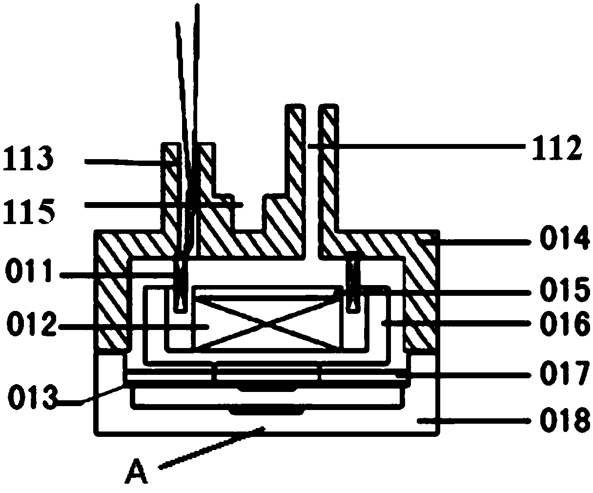
[0044] refer to figure 1 , image 3 as well as Figure 5 , Embodiment 1 of the present invention is a waterproof bone conduction earphone, the housing includes an upper shell 018 and a lower shell 014, the vibration transmitting part A is arranged on the upper shell 018, and the open end of the upper shell 018 is sealed and connected to the upper side of the lower shell 014 , forming a waterproof airtight space, and the bone conduction component is arranged in the airtight space. In this embodiment, both the upper shell 018 and the lower shell 014 are cylindrical shells with one end open, and they form a cylindrical waterproof sealed space. The sealed housing can also adopt other forms, which will be described in detail in other embodiments.
[0045] When in use, the vibration transmission part A is in close contact with the human ear to form bone conduction to the sound. In this embodiment, the vibration transmitting part A is a part of the upper shell 018 , and the vibra...
no. 2 example
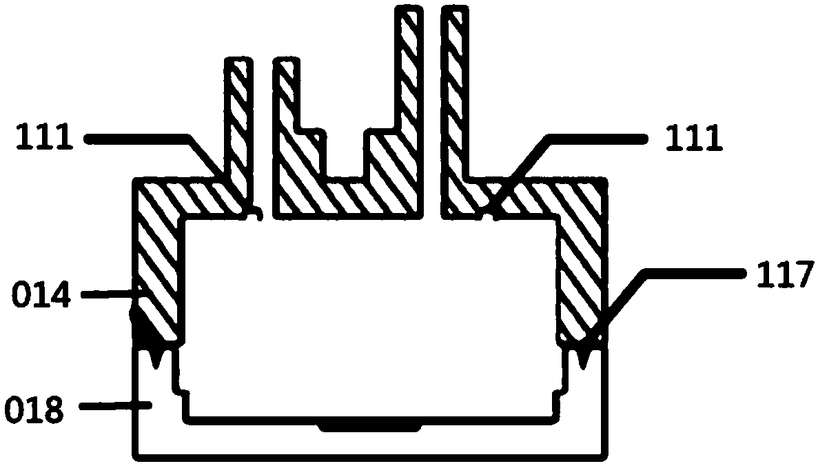
[0059] For the waterproof structure of the waterproof bone conduction earphone in Embodiment 1, it is necessary to provide a corresponding manufacturing process. Specifically, the lower shell 014 protrudes to form a tubular threading hole 113 and a waterproof test hole 112, which includes steps:
[0060] S1. Install the bone conduction assembly into the upper case 018 and the lower case 014, lead the wire of the voice coil 011 out through the threading hole, and seal the upper case 018 and the lower case 014 to form the waterproof airtight space;
[0061] S2. The protruding threading hole 113 and the waterproof test hole 112 of the lower case pass through the corresponding through hole of the main body case, and the lower case is connected with the main body case;
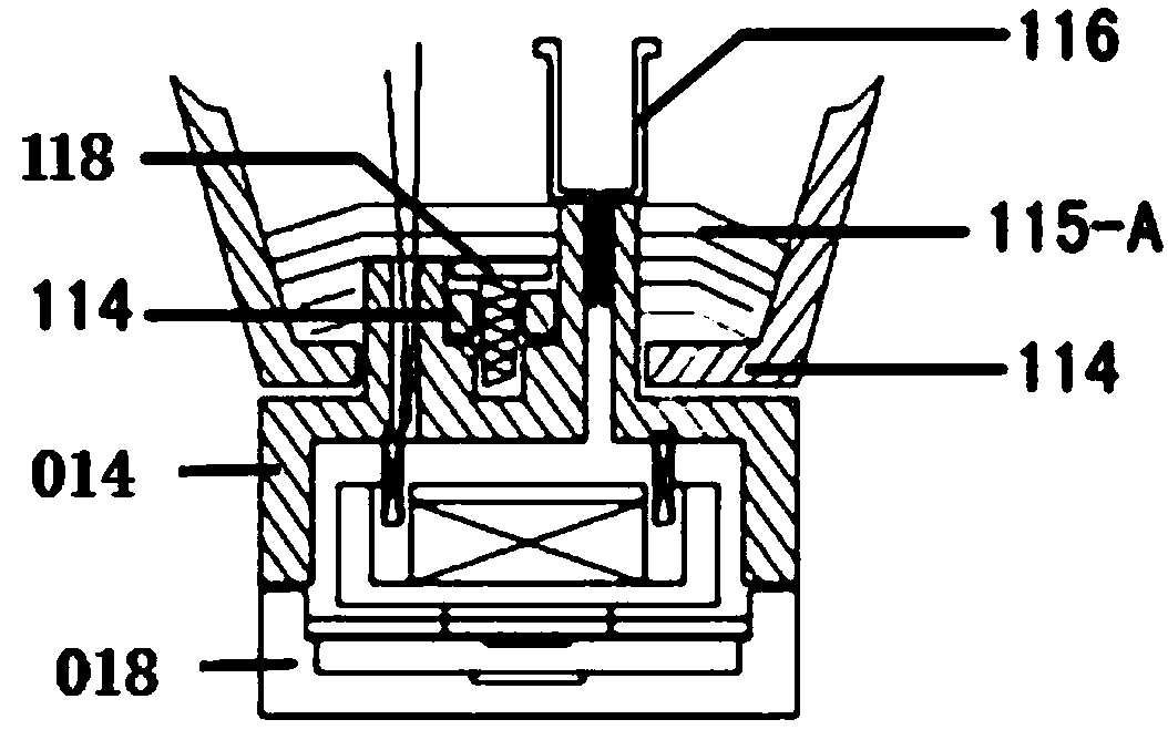
[0062] S3. Apply the first layer of waterproof glue 115-A to seal the threading hole and the connection gap between the lower shell and the main shell, such as image 3 shown;
[0063] S4. Pressurize the waterproo...
no. 3 example
[0068] The third embodiment differs from the first embodiment in the configuration of the vibration-transmitting plate fixing member 017 .
[0069] In this example, if Figure 9 As shown, the vibration-transmitting plate fixing member 017 is an annular structure. The diameter of the annular fixing part 017 is slightly smaller than the inner diameter of the cylindrical upper and lower shells in the first embodiment, so that it can be put into the waterproof airtight space formed by the upper and lower shells. The length of the fixing part 017 is the distance from the inner surface of the bottom of the lower shell 014 to the vibration transmission plate 013, refer to Figure 8 . Therefore, one end of the fixing member 017 abuts against the inner surface of the bottom of the lower shell 014 , and the other end abuts against the edge of the vibration transmitting piece 013 , forming a fixation to the vibration transmitting piece 013 . Compared with the fixing method in the firs...
PUM
 Abstract
Description
Claims
Application Information
 - R&D
- Intellectual Property
- Life Sciences
- Materials
- Tech Scout
- Unparalleled Data Quality
- Higher Quality Content
- 60% Fewer Hallucinations
Browse by: Latest US Patents, China's latest patents, Technical Efficacy Thesaurus, Application Domain, Technology Topic, Popular Technical Reports.
© 2025 PatSnap. All rights reserved.Legal|Privacy policy|Modern Slavery Act Transparency Statement|Sitemap|About US| Contact US: help@patsnap.com


