
Switch-off energy recycling method and circuit

A technology of energy recovery and circuit, which is applied in the direction of circuit devices, battery circuit devices, collectors, etc., can solve the problems of high switch temperature and large switch turn-off loss, and achieve the effect of reducing loss

Active Publication Date: 2018-03-13
MORNSUN GUANGZHOU SCI & TECH
View PDF4 Cites 3 Cited by
  • Summary
  • Abstract
  • Description
  • Claims
  • Application Information

AI Technical Summary

Problems solved by technology

[0004] (1) The switch off loss is large;
[0005] (2) The turn-off energy is all converted into heat energy, resulting in an increase in the temperature of the switch

Method used


Image

  • Switch-off energy recycling method and circuit
  • Switch-off energy recycling method and circuit
  • Switch-off energy recycling method and circuit

Examples


no. 1 example

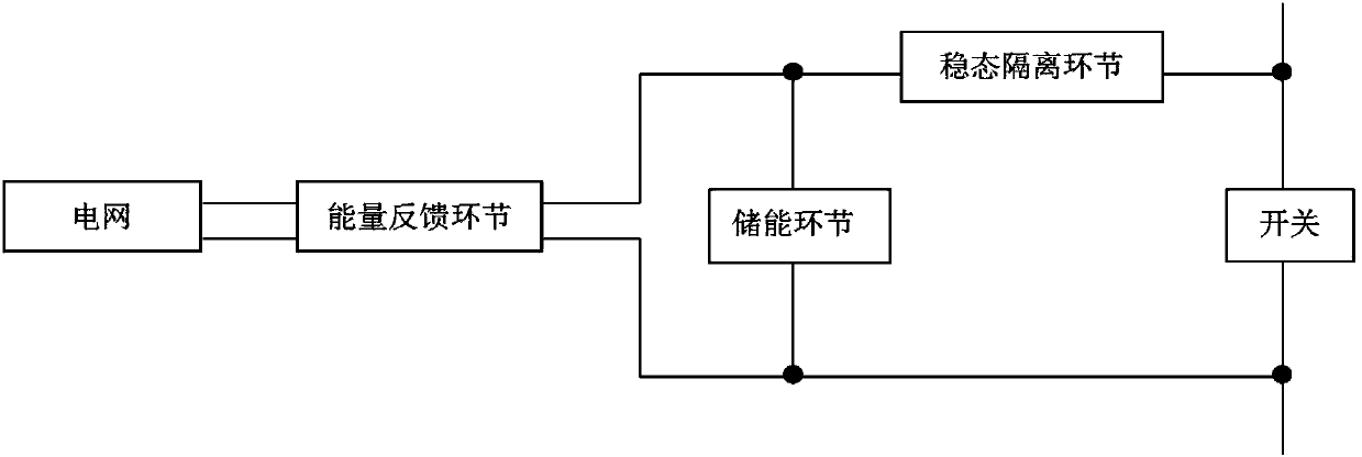
[0036] figure 2 It is a schematic diagram of the first embodiment of the shut-off energy recovery circuit of the switch of the present invention, wherein the steady-state isolation module is composed of capacitor C1, the energy storage module is composed of capacitor C2, and the energy feedback module is an AC-DC converter (or switch power supply), the AC-DC converter includes a rectifier bridge B1 and a flyback circuit, and the flyback circuit includes a transformer T1, a primary circuit formed by a primary winding of the transformer T1, and a secondary circuit formed by a secondary winding of the transformer T1; The primary side circuit of the flyback circuit also includes a switch G1 and a capacitor C3, and the secondary side circuit also includes a diode D2.

[0037] The connection relationship of the first embodiment of the turn-off energy recovery circuit of the switch of the present invention is as follows:

[0038] One end of the capacitor C1 is taken as the first in...

no. 2 example

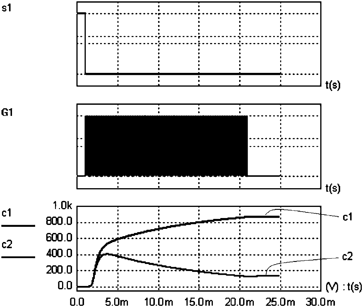
[0050] The principle diagram of the energy recovery circuit for turning off the switch in the second embodiment is the same as that in the first embodiment, but the control method is different. The rectifier bridge B1, capacitor C3, switch G1, transformer T1 and diode D2 constitute an AC / DC flyback circuit module. The operation of the AC / DC flyback circuit module is independent, determined by the voltage of capacitor C3 and controlled by switch S1 Signal is irrelevant. When the voltage of the capacitor C3 is greater than the working voltage of the flyback circuit, the flyback circuit works, and when the voltage of C3 is lower than the working voltage of the flyback circuit, the flyback circuit stops working. When this structure is adopted, off-the-shelf AC / DC modules can be used without redesigning the circuit.


PUM


Abstract

The invention provides a switch-off energy recycling method and circuit. The switch-off energy recycling circuit comprises a capacitor C1, a capacitor C2 and an AC-DC converter, wherein the AC-DC converter comprises a rectification bridge B1 and a flyback circuit, the flyback circuit comprises a transformer T1, a primary circuit and a secondary circuit, a primary winding of the transformer T1 forms the primary circuit, a secondary winding of the transformer T1 forms the secondary circuit, one end of the capacitor C1 is led out and used as a first input end of the switch-off energy recycling circuit, the other end of the capacitor C1 is connected with one end of the capacitor C2, the other end of the capacitor C2 is led out and used as a second input end of the switch-off energy recycling circuit, one end of the capacitor C2 is further connected with an AC input end of the rectification bridge B1, the other end of the capacitor C2 is further connected with another one AC input end of the rectification bridge B1, a DC output end of the rectification bridge B1 is connected with the primary circuit of the flyback circuit, and an output end of the secondary circuit of the flyback circuit is led out and used as an output end of the switch-off energy recycling circuit.

Description

technical field [0001] The invention relates to a method and a circuit for recovering the shut-off energy of a switch, in particular to a method and a circuit for recovering the shut-off energy of a solid-state circuit breaker. Background technique [0002] During the shutdown process of solid state circuit breakers, losses occur in the overlapping region of voltage and current. A relatively simple method to reduce the turn-off loss is to connect a capacitor in parallel to the switch, through which the voltage rise rate during the turn-off process of the switch is reduced, and the overlapping area of ​​voltage and current is reduced, thereby reducing the turn-off loss. Although this method can reduce the loss during turn-off, the energy stored in the capacitor will be lost in the switch when the switch is turned on, increasing the turn-on loss. The turn-off energy is all converted into heat energy, causing the temperature of the switch to rise. [0003] Therefore, the curr...

Claims


Application Information

Patent Timeline
IPC IPC(8): H02J7/34H02M7/219H02M3/335
CPCH02J7/345H02M3/33523H02M7/219
Inventor 王志燊尹向阳
Owner MORNSUN GUANGZHOU SCI & TECH
Learn More