
Power distribution cabinet cooling method

A technology for power distribution cabinets and cabinets, applied in the field of power equipment manufacturing, can solve problems such as single method, damage to equipment, and failure to prevent dust from entering the interior of the cabinet, and achieve the effects of convenient use and simple structure

Active Publication Date: 2018-03-13
中鼎(吉林)智能制造工程有限公司
View PDF4 Cites 17 Cited by
  • Summary
  • Abstract
  • Description
  • Claims
  • Application Information

AI Technical Summary

Problems solved by technology

The power distribution cabinet is equipped with a fan and an electronic thermometer, and a vent is opened on the cabinet body. During this process, the electronic thermometer detects the indoor temperature. When the temperature rises, the fan is controlled to work to achieve the effect of heat protection and heat dissipation. However, the opening of the air vent will introduce dust or other impurities from the outside into the power distribution cabinet. Although there is a rainproof plate, it does not prevent dust from entering the cabinet. When the fan is started, the dust will adhere to the circuit components. Damage the equipment, and at the same time, the power distribution cabinet only cools down through the fan, the method is single, and the cooling effect is not obvious

Method used


Image

  • Power distribution cabinet cooling method
  • Power distribution cabinet cooling method

Examples


Embodiment Construction

[0022] Further detailed explanation through specific implementation mode below:

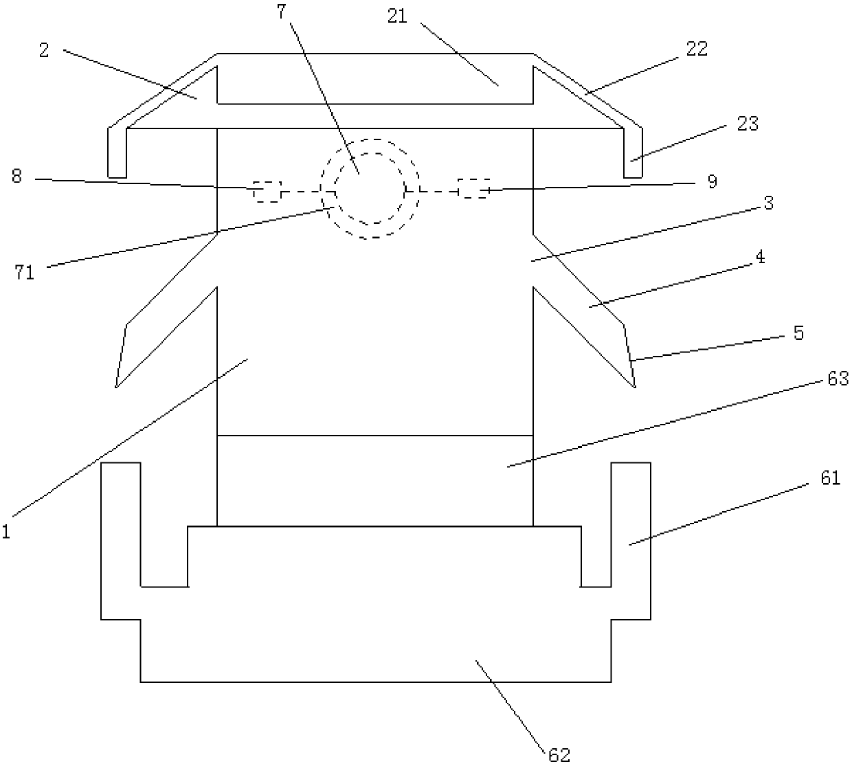
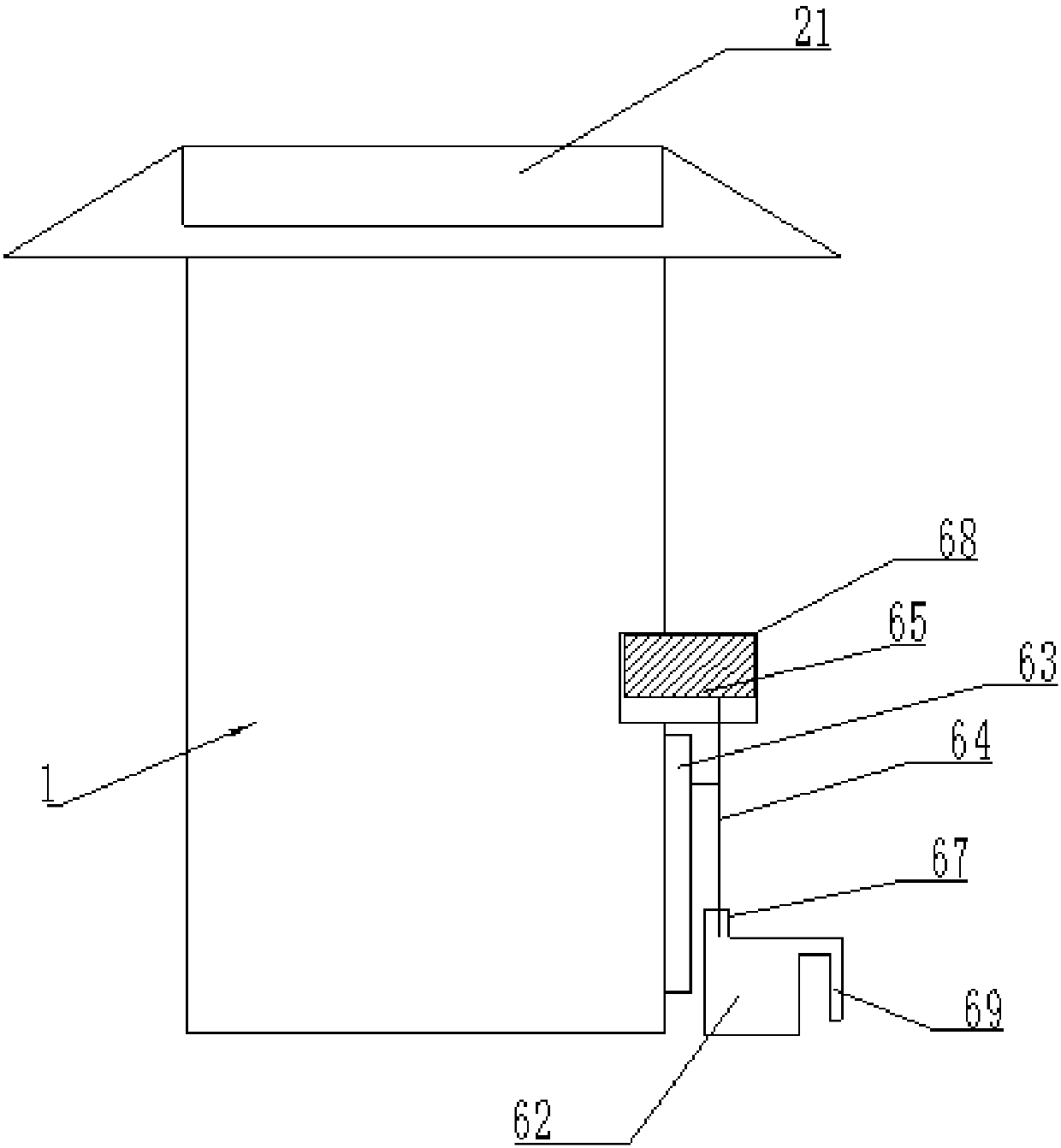
[0023] The reference signs in the drawings of the description include: cabinet 1, cleaning device 2, water collection tank 21, drainage pipe 22, drainage water pipe 23, vent 3, vent pipe 4, dust removal net 5, water receiving pipe 61, water storage tank 62, sponge layer 63, cotton rope 64, inflatable air bag 65, cotton rope hole 67, mesh cage 68, drainage pipe 69, fan 7, dustproof cover 71, temperature sensor 8, microcontroller 9.

[0024] Such as figure 1 As shown, a power distribution cabinet for cooling and dust removal includes a cabinet body 1 and a water storage device 2, a cleaning device is fixedly installed above the cabinet body, and a water collection tank 21 is opened in the center of the cleaning device 2. When rainy days come, Rainwater can be stored in the sump 21, and when the temperature rises, the water above the cabinet 1 can properly cool the top of the cabinet, and drainage ...


PUM


Abstract

The invention belongs to the power equipment manufacturing field and specifically discloses a power distribution cabinet cooling method. The power distribution cabinet cooling method comprises the following steps of: Step 1, a micro controller controls an electromagnetic valve on a drainage water pipe to be switched off; Step 2, the micro controller controls the electromagnetic valve on the drainage water pipe to be switched on, and after a rainwater tank is filled with water, the water flows into a water receiving pipeline from the drainage water pipe and enters a water storage tank so as tobe stored; Step 3, the micro controller controls a fan to operate when the temperature in the cabinet body rises to 35 DEG C, and the micro controller controls the fan to stop running when the temperature of a temperature sensor is lower than 35 DEG C; Step 4, when the temperature in the cabinet body rises to 40 DEG C, an expansion airbag is expanded; Step 5, after the expansion airbag expands, the bottom end of a cotton rope penetrates deeply into a cotton rope hole so as to be in contact with the water in the water storage tank, and then the water is absorbed by the cotton rope and diffusesto a sponge layer. In the invention, by storing the rainwater, in combination with the control of the fan inside the power distribution cabinet and the utilization of the rainwater by an outer shell of the power distribution cabinet, dual cooling of the power distribution cabinet is achieved.

Description

technical field [0001] The invention relates to the field of electric equipment manufacturing, in particular to a cooling method for a power distribution cabinet. Background technique [0002] Power equipment is mainly divided into two categories: power generation equipment and power supply equipment. Power generation equipment is mainly steam turbines, gas turbines, water turbines, power station boilers, generators, transformers, etc. Power supply equipment is mainly transmission lines of various voltage levels, transformers, contactors, etc. device and so on. [0003] Power distribution cabinets are often used in the installation and use of power facilities. If the power distribution cabinet is used for a long time, the weather is too hot or the sun is exposed for a long time, the internal temperature will become very high. If it is not dissipated in time, the internal components will be damaged. burnt or damaged. [0004] In order to solve the above problems, the prior ...

Claims


Application Information

Patent Timeline
Patent Type & Authority Applications(China)
IPC IPC(8): H02B1/56H02B3/00B08B17/02
CPCB08B17/02H02B1/565H02B3/00
Inventor 邱红光
Owner 中鼎(吉林)智能制造工程有限公司
Learn More