A low-speed impact test fixture with continuously adjustable impact angle

A technology of low-speed impact and test fixture, which is applied in the direction of impact test, machine/structural component test, measuring device, etc. It can solve the problems of increased test cost and impossibility of plate impact test, etc., and achieves simple structure, small footprint, and easy The effect of the operation

Active Publication Date: 2019-08-13
CIVIL AVIATION UNIV OF CHINA
View PDF8 Cites 0 Cited by
  • Summary
  • Abstract
  • Description
  • Claims
  • Application Information

AI Technical Summary

Problems solved by technology

Drop hammer and pendulum impact test benches can only be placed horizontally. The punch impacts the specimen head-on, and then studies the remaining strength, fatigue life and damage mode of the specimen after being impacted by the front. It is very important for the variable-angle impact test. Difficult to realize; because the impact resistance of metal materials is affected by its rolling direction, the existing solution is generally to take metal materials in different rolling directions for impact, but it is not possible to impact the plate with varying angles and rolling directions Test; and the impact resistance of composite materials is affected by the layup sequence and angle. If impact samples are made separately for each layup sequence and angle, the test cost will be greatly increased
The air cannon is suitable for high-speed impact tests, but not suitable for simulating low-speed impact processes such as tools and gravel.

Method used


Image

  • A low-speed impact test fixture with continuously adjustable impact angle
  • A low-speed impact test fixture with continuously adjustable impact angle

Examples


Embodiment Construction

[0012] The low-speed impact test jig with continuously adjustable impact angle provided by the present invention will be described in detail below in conjunction with specific embodiments and accompanying drawings:

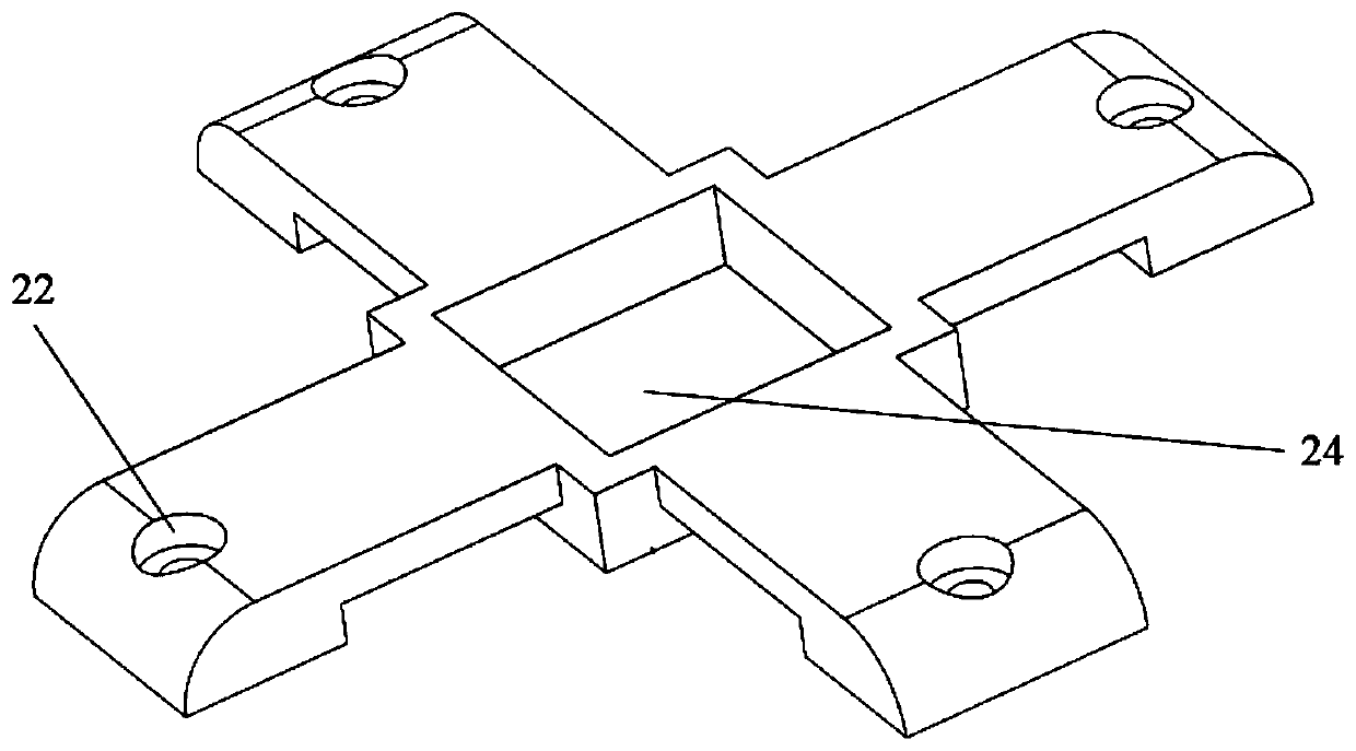
[0013] Such as figure 1 As shown, the low-speed impact test jig provided by the present invention includes a jig upper splint 2, a plane corner angle disc 4, a test piece fixing plate 5, a top plate 6, a pointer 7, a centering triangle block 8, and a rotating shaft 9. , elevation angle plate 10, baffle plate 11, square head support column 12, connecting shaft 13, round head support column 14, upper fixing nut 16, lower fixing nut 17, supporting base plate 18, laser transmitter 19, supporting column 20, fixing Plate 21; wherein the fixed plate 21 is arranged horizontally; the upper and lower ends of the four supporting columns 20 are respectively connected to the bottom surface of the supporting base plate 18 and the four corners of the surface of the fixing plate ...


PUM


Abstract

An impact angle continuously adjustable low-speed impact test clamp comprises a clamp upper clamping plate, a planar rotation angle scale, a test piece fixing plate, a top plate, a pointer, a centringtriangular block, a rotating shaft, an elevation angle scale, a baffle, a square-head supporting column, a connecting shaft, a bulletheaded supporting column, an upper fixing nut, a lower fixing nut,a supporting bottom plate, a laser emitter, a supporting cylinder and a fixing plate. The impact angle continuously adjustable low-speed impact test clamp provided by the present invention can adjustmultiple angles of a test piece continuously, and can realize the planar rotation of multiple directions of the test piece, so that on the condition of not changing an original impact mode, and by aspecial mechanical structure, the impact angle continuously adjustable low-speed impact test clamp satisfies the impact demands of different angles and directions, is low in cost, simple in structure,strong in transportability and small in floor space, is easy to operate, enables the cost for manufacturing the test clamps of different angles to be reduced substantially, and can supplement or substitute for the conventional test equipment in function to reach the test demands.

Description

technical field [0001] The invention belongs to the technical field of impact testing devices, and in particular relates to a low-speed impact test fixture whose impact angle can be continuously adjusted. Background technique [0002] Foreign object impact damage is a common form of structural damage, which is characterized by variable impact velocity and impact angle. Impact damage can be caused by a variety of causes, such as in the aerospace field, which include runway debris, hail, damage from aircraft maintenance or repair (such as dropped tools), accidental collisions with ground maintenance vehicles or luggage carts, and broken down debris impact and so on. Metal and composite material sheets are widely used in the aerospace field, and are susceptible to various foreign object damage during manufacturing and use, such as aluminum alloy fuselage skin, composite wing leading edge, titanium alloy or superalloy engine fan Blades and the like are vulnerable to impacts fr...

Claims


Application Information

Patent Timeline
Patent Type & Authority Patents(China)
IPC IPC(8): G01M7/08
CPCG01M7/08
Inventor 陈亚军季春明宋肖肖王付胜张汛涛
Owner CIVIL AVIATION UNIV OF CHINA
Why Eureka
Try Eureka