A medium and low temperature oil bath tempering equipment

A low-temperature oil bath and equipment technology, applied in heat treatment equipment, heat treatment baths, furnaces, etc., can solve the problems of low production efficiency and difficulty in adapting to mass production in vacuum tempering furnaces, and achieve high tempering temperature, uniform tempering temperature, The effect of stable performance

Active Publication Date: 2019-06-18
HAINING XINYI MACHINERY & ELECTRICAL
View PDF6 Cites 0 Cited by
  • Summary
  • Abstract
  • Description
  • Claims
  • Application Information

AI Technical Summary

Problems solved by technology

For example, the patent application number 2010102014547 discloses a mesh-belt hot blast tempering furnace equipped with a large rotating fan to keep the temperature in the furnace uniform; the patent application number 2014108037540 discloses a vertical continuous tempering furnace , using the upper-supply and lower-return air supply structure to improve temperature uniformity and reduce the equipment footprint; the patent application number is 2007100246552 discloses a push rod type continuous vacuum tempering and annealing multi-purpose furnace, the purpose is to solve the vacuum tempering furnace production Low efficiency, difficult to adapt to the needs of mass production

Method used


Image

  • A medium and low temperature oil bath tempering equipment

Examples


Embodiment Construction

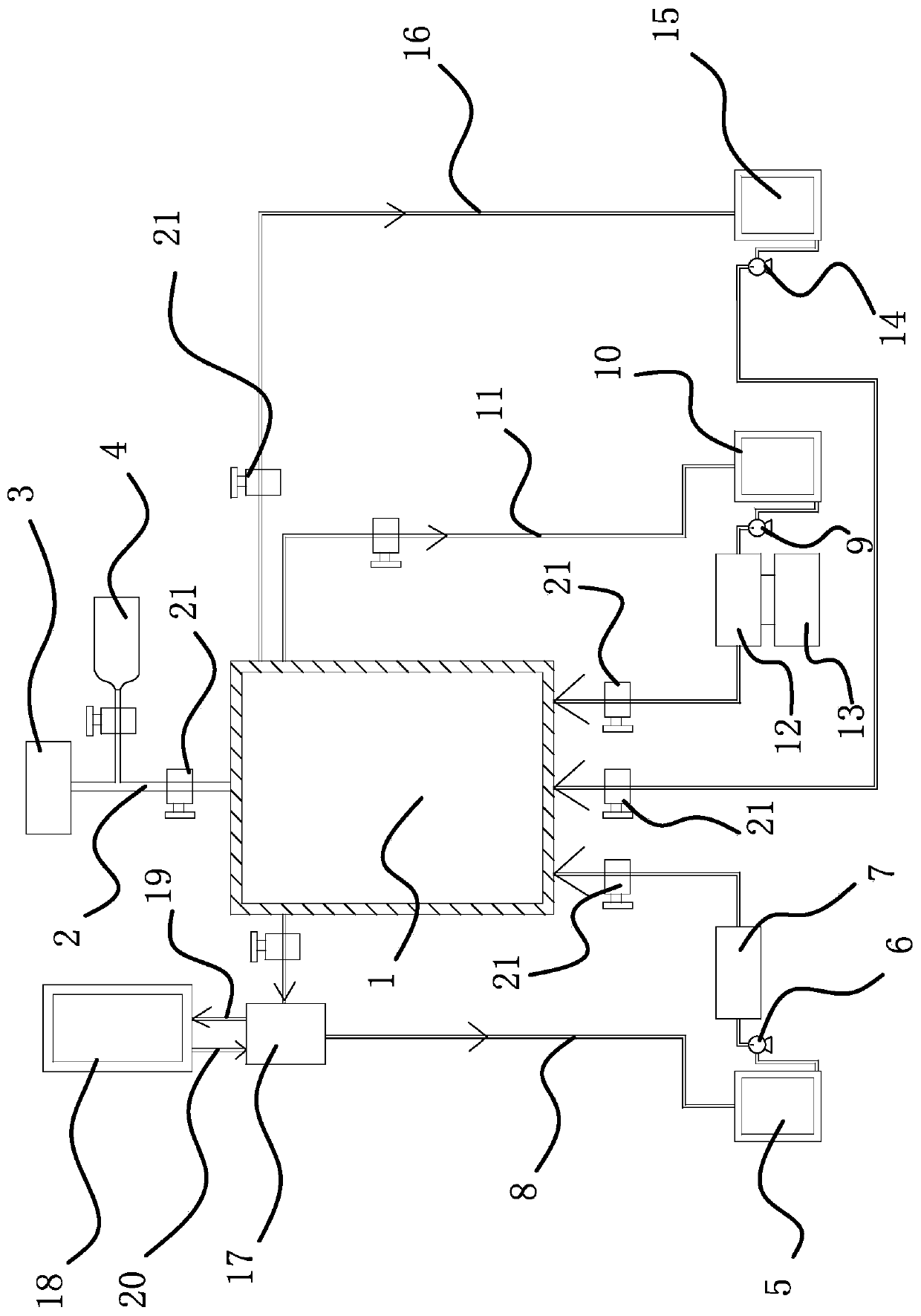
[0023] The following are specific embodiments of the present invention and in conjunction with the accompanying drawings, the technical solutions of the present invention are further described, but the present invention is not limited to these embodiments.

[0024] Such as figure 1 As shown, the medium and low temperature oil bath tempering equipment includes a furnace body 1, a vacuum protection atmosphere system, a hot oil circulation system, a cold oil circulation system, and a cleaning circulation system. It is characterized in that the vacuum protection atmosphere system includes three ventilation pipes 2. The vacuum pump 3 connected to the inner cavity of the furnace body 1 through the three-way gas pipe 2 and the steel cylinder 4 for storing inert gas, the steel cylinder 4 is connected to the three-way gas pipe 2; the thermal oil circulation system includes a thermal oil tank 5, a first thermal oil pump 6, The heater 7 and the thermal oil circulation pipeline 8 connecte...


PUM


Abstract

The invention provides medium and low temperature oil bath tempering equipment. The medium and low temperature oil bath tempering equipment comprises a furnace body, a vacuumizing protective atmosphere system, a hot oil circulation system and a cold oil circulation system. The vacuumizing protective atmosphere system comprises a tee joint gas pipe, a vacuum pump communicating with an inner cavityof the furnace body through the tee joint gas pipe, and a steel cylinder for storing inert gas, and the steel cylinder is connected with the tee joint gas pipe. The hot oil circulation system comprises a hot oil tank, a first hot oil pump, a heater and a hot oil circulation pipeline with the two ends communicating with the furnace body, and the hot oil tank, the first hot oil pump and the heater are sequentially connected with the hot oil circulation pipeline. The cold oil circulation system comprises a second hot oil pump, a cold oil tank and a cold oil circulation pipeline with the two endscommunicating with the furnace body, and the second hot oil pump and the cold oil tank are both connected with the cold oil circulation pipeline. Tempering oil is heated and subjected to heat preservation under a completely sealed condition, and aging caused by oxidation when the tempering oil makes contact with air is eliminated. Meanwhile, oil fumes are eliminated, and the higher tempering temperature is obtained. After tempering is finished, the hot oil circulation pipeline is closed, the cold oil circulation pipeline is opened, cold oil is injected into the furnace body, a workpiece is cooled through the cold oil, and the recycled cold oil flows back to the cold oil tank.

Description

technical field [0001] The invention belongs to the equipment used for medium and low temperature tempering treatment of parts in the metal heat treatment industry. Background technique [0002] Tempering is a heat treatment process in which the quenched workpiece is heated to an appropriate temperature below the critical point AC1 for a certain period of time, and then cooled by a method that meets the requirements to obtain the required structure and properties. [0003] When implementing the tempering process, a variety of tempering equipment can be used. According to different heating sources, there are electric heating and gas heating tempering furnaces; according to different equipment structures, there are box type tempering furnaces, well type tempering furnaces, etc.; according to different workpiece transmission methods, there are mesh belt type tempering furnaces, trolley type tempering furnaces, etc. ; and according to the "heat transfer medium", there are air t...

Claims


Application Information

Patent Timeline
Patent Type & Authority Patents(China)
IPC IPC(8): C21D1/50C21D9/00C21D1/74
CPCC21D1/50C21D1/74C21D9/00
Inventor 怀华培高麟徐金良戴立强
Owner HAINING XINYI MACHINERY & ELECTRICAL
Why Eureka
Try Eureka