
Copper lifting lug shearing and flattening device

A lifting lug and leveling technology, which is used in shearing devices, shearing machines, other manufacturing equipment/tools, etc., can solve the problems of unqualified lifting lugs, poor reliability, and difficulty in adjusting the gap between upper and lower blades, so as to improve production efficiency. and production quality, saving operating costs and time, easy disassembly and maintenance

Pending Publication Date: 2018-03-13
JINCHUAN GROUP LIMITED
View PDF0 Cites 3 Cited by
  • Summary
  • Abstract
  • Description
  • Claims
  • Application Information

AI Technical Summary

Problems solved by technology

[0003] There are mainly two types of existing shear earphone structures, one is the pendulum shear earphone, that is, one end of the upper and lower blades is hinged, and the moving knife at the other end moves up and down to complete the shearing. Because it is difficult to adjust the gap between the upper and lower blades when cutting thin plates, The shearing force is large, and many problems have been exposed during use. The specific manifestations are prone to equipment accidents or failures such as tool holder breakage, blade chipping, and frame breakage; the other is roller shearing. The rotation of the cutter and the upper and lower rolls completes the shearing. The structure reliability of the existing device is poor, and the edges of the copper lifting lugs will be wavy, uneven, and curled after shearing, resulting in unqualified lifting lugs and affecting subsequent orders. ear process

Method used


Image

  • Copper lifting lug shearing and flattening device
  • Copper lifting lug shearing and flattening device
  • Copper lifting lug shearing and flattening device

Examples


Embodiment Construction

[0026] The present invention will be further described below in conjunction with the accompanying drawings and specific embodiments.

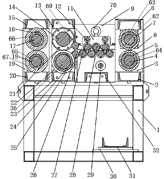
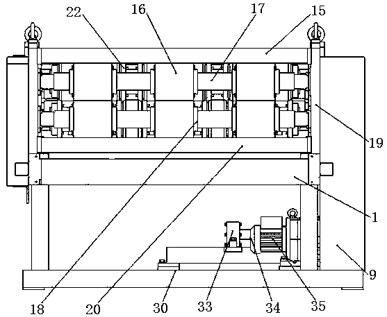
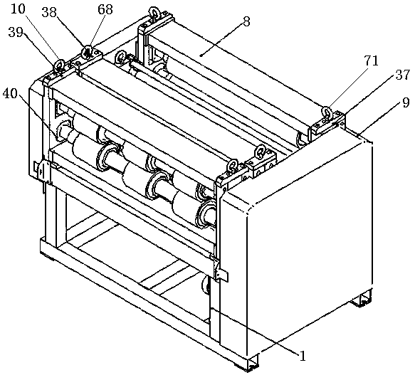
[0027] like Figure 1-6As shown, a copper lifting lug shearing and leveling device includes a frame 1 and a feed module arranged on the frame 1, a rolling shear bar module, a copper lifting lug straightening module, a flattening module and a transmission system, The feed module is arranged on the feed end of the rolling shear strip module, and the feed module includes the feed baffle 19 fixed on the left and right ends of the frame 1 and the feed roller shaft bearing seat 40 installed on the feed baffle. Upper feeding roller shaft 17 and lower feeding roller shaft 65 are installed up and down between the material roller bearing housing 40, and upper feeding roller shaft 17 is provided with three upper feeding roller shaft sleeves 66 and each upper feeding roller The shaft sleeve 66 is provided with an upper feed roller 16, and the lower feed r...


PUM


Abstract

The invention discloses a copper lifting lug shearing and flattening device. The device mainly comprises a feeding module, a rolling and shearing strip module, a copper lifting lug straightening module, a flattening module and a transmission system. Power is transmitted to the feeding module, the rolling and shearing strip module, the copper lifting lug straightening module and the flattening module through the transmission system. A copper starting sheet can be effectively shorn into copper lifting lugs of certain specifications and sizes, and shaping of the copper lifting lugs is achieved; and the problems that at present, a tool rest is fractured, a blade is broken, and edges of copper lifting lugs deform and curl after shearing is completed are effectively solved. According to the copper lifting lug shearing and flattening device, modularized design is adopted; the copper lifting lug shearing and flattening device is compact in structure and high in reliability and modularization degree, feeding, shearing, straightening and flattening are integrated, and the copper lifting lugs can be shorn, straightened and flattened efficiently; production efficiency and production quality oflug pieces are greatly improved; all the modules are easy to demount, maintain and upgrade; and operating cost and time are saved for an enterprise.

Description

technical field [0001] The invention belongs to the field of nonferrous metallurgical equipment, and in particular relates to a copper lifting lug shearing and leveling device. Background technique [0002] Electrolysis process is currently one of the main ways to obtain high-purity copper. The electrolysis process is widely used in the production process of copper and other metal materials. In the electrolysis process, the manufacture of the starter sheet is a main work content in the electrolysis process. The structure of the starting plate consists of three parts, the first is the plate itself; the second is the lifting lug; the third is the conductive rod. The raw material used for the lifting lug is the copper lifting lug of the specified size cut from the copper starter plate. The lugs are folded in half by the processing unit and then nailed to the starter. Copper electrolysis plants need to manufacture a large number of starters and lifting lugs every day. [000...

Claims


Application Information

Patent Timeline
IPC IPC(8): B23P23/04B23D19/06
CPCB23D19/06B23P23/04
Inventor 杜小猛宿展张晶晶梁文江刘浩东
Owner JINCHUAN GROUP LIMITED
Learn More