Weld joint tracking welding device for U-shaped rib plate

A technology of welding devices and ribs, applied in welding equipment, welding accessories, electrode support devices, etc., can solve the problems of high labor intensity, long adjustment time, and high load-bearing requirements for workers, and achieve simple structure, convenient maintenance, and impact resistance. strong effect

Inactive Publication Date: 2018-03-13
WUXI YANGTONG MACHINERY EQUIP
View PDF0 Cites 1 Cited by
  • Summary
  • Abstract
  • Description
  • Claims
  • Application Information

AI Technical Summary

Problems solved by technology

[0002] U-shaped ribs (also known as closed ribs) are a kind of reinforced ribs widely used in the bearing boxes of highways and railway bridges, and the bearing joints of large weighing instruments. The load-bearing requirements are high, and generally all require full For penetration welding, since the rib itself has a certain angle, and a groove of about 40 degrees is also processed, the welding position is very special, and the general conventional welding position cannot meet the requirements. The workpiece is turned to a 30-degree inclined position, and a semi-automatic welding trolley is used for single-wire gas shielded welding. Each weld must be welded with a trolley, and an operator must be taken to watch it. Due to the influence of cables, the welding section must be stopped for a while. , move the cable, etc., the operation is cumbersome, and the labor intensity of the workers is high. After welding the weld on one side, use the crane to turn the flip table to the other side by 30 degrees, and then weld the weld on the other side, and because the weld The special location requires adjustment of the new welding torch, which takes a long time to adjust and is very inconvenient to operate

Method used


Image

  • Weld joint tracking welding device for U-shaped rib plate
  • Weld joint tracking welding device for U-shaped rib plate

Examples


Embodiment Construction

[0012] The specific implementation manner of the present invention will be described below in conjunction with the accompanying drawings.

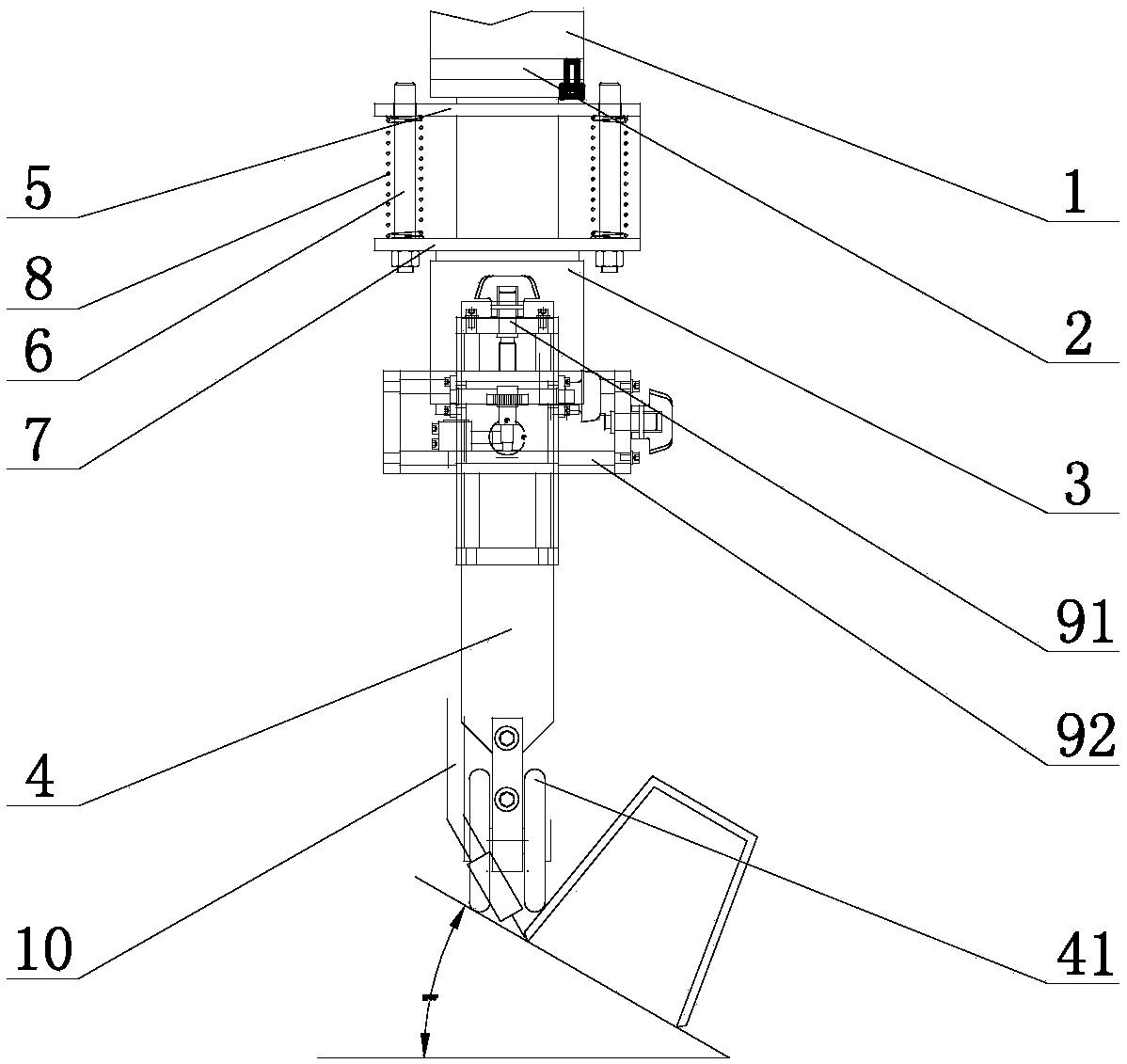
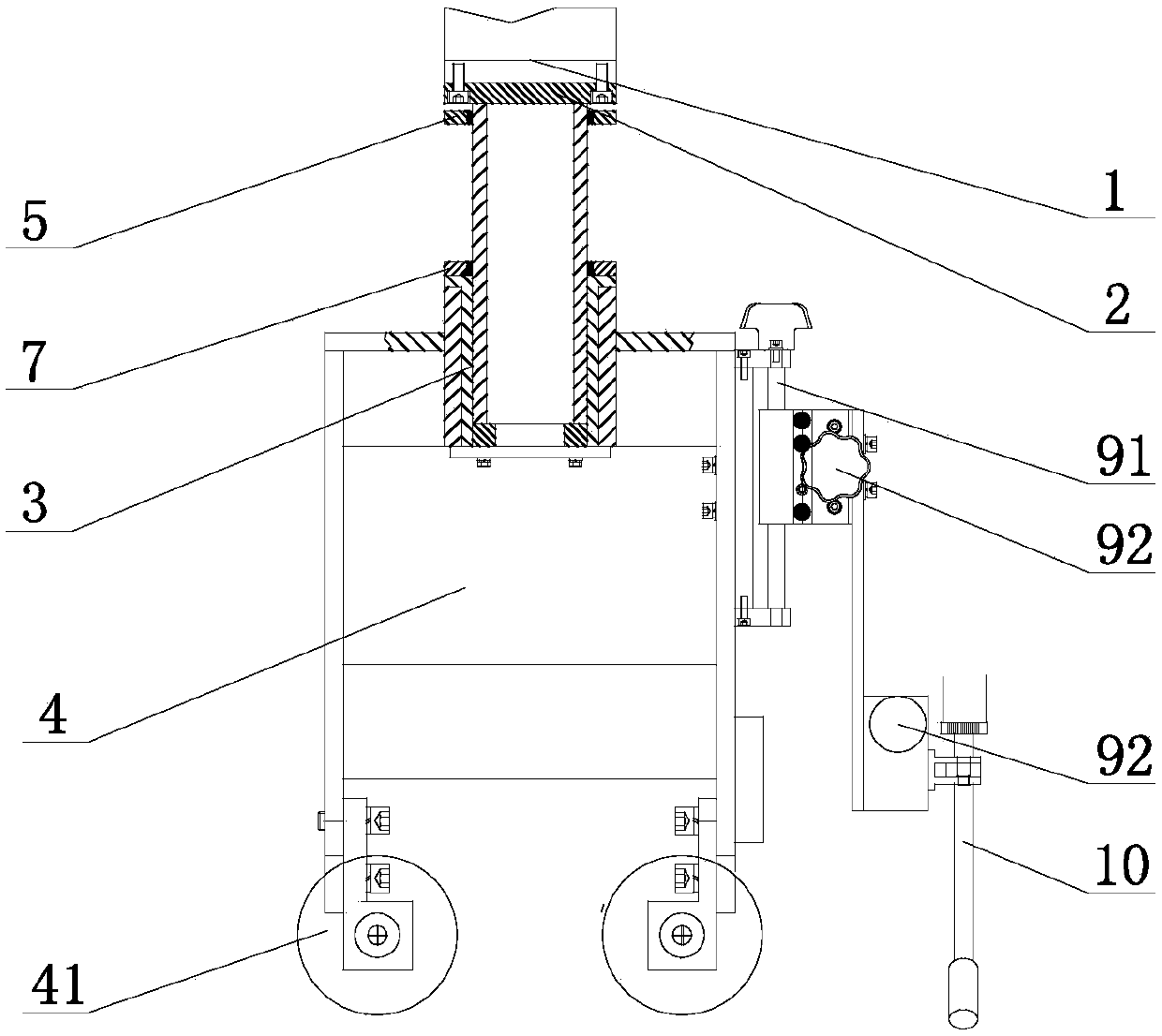
[0013] Such as figure 1 , figure 2 As shown, the U-shaped rib seam tracking welding device in this embodiment includes a lifting welding arm 1 and a welding torch adjustment device. The sliding shaft 2 is fixed under the lifting welding arm 1, and the lower end of the sliding shaft 2 is connected to the arc guide frame 4 through the guide sleeve 3 , the guide post mounting plate 5 is fixed on the sliding shaft 2, the guide post 6 is installed on both sides of the guide post mounting plate 5, the lower end of the guide post 6 is fixedly connected with the guide post fixing plate 7 connected to the guide sleeve 3, and the outside of the guide post 6 is fixed with Compression spring 8, guide wheel 41 is installed on the lower end of arc guide frame 4, welding torch adjustment device includes welding torch lifting fine adjustment slide plate...


PUM


Abstract

The invention relates to a U-shaped rib seam tracking welding device, which includes a lifting welding arm and a welding torch adjustment device. A sliding shaft is fixed under the lifting welding arm. The lower end of the sliding shaft is connected to the arc guide frame through a guide sleeve. Fix the guide post mounting plate, guide posts are installed on both sides of the guide post mounting plate, the lower end of the guide post is fixedly connected with the guide post fixing plate connected to the guide sleeve, a compression spring is fixed on the outside of the guide post, and the The guide wheel is installed at the lower end of the arc guide frame, the welding torch adjustment device is fixed on one side of the arc guide frame, the welding torch is fixed on the welding torch adjustment device, the welding seam tracking welding device of the U-shaped rib plate is used, and the lifting welding arm adopts a square guide rail to prevent Impact, strong impact resistance, the arc guide frame is pressed by springs, the pressing force is adjustable, the tracking is sensitive, the guide wheel guide resistance is small, the welding torch is connected through the welding torch adjustment device, and the welding torch can be quickly adjusted. The whole mechanism has no electrical parts. Simple structure and easy maintenance.

Description

technical field [0001] The invention relates to a welding device, in particular to a U-shaped rib seam tracking welding device. Background technique [0002] U-shaped ribs (also known as closed ribs) are a kind of reinforced ribs widely used in the bearing boxes of highways and railway bridges, and the bearing joints of large weighing instruments. The load-bearing requirements are high, and generally all require full For penetration welding, since the rib itself has a certain angle, and a groove of about 40 degrees is also processed, the welding position is very special, and the general conventional welding position cannot meet the requirements. The workpiece is turned to a 30-degree inclined position, and a semi-automatic welding trolley is used for single-wire gas shielded welding. Each weld must be welded with a trolley, and an operator must be taken to watch it. Due to the influence of cables, the welding section must be stopped for a while. , move the cable, etc., the ...

Claims


Application Information

Patent Timeline
IPC IPC(8): B23K9/127B23K9/28B23K9/32
CPCB23K9/1278B23K9/28B23K9/32
Inventor 贾盛凯
Owner WUXI YANGTONG MACHINERY EQUIP
Why Eureka
Try Eureka