Single arm outer fixation frame

An external fixator and single-arm technology, which is applied in the field of medical devices, can solve the problems of prolonging the treatment time, not being able to take advantage of the space advantage of the external fixator, and the limitation of the transmission distance of the lateral mass of the external fixator, so as to achieve a wide range of applications, accelerate growth and Effects of healing and shortening the treatment time

Pending Publication Date: 2018-03-13
GUANGZHOU SUN SHING BIOTECH CO LTD
View PDF0 Cites 6 Cited by
  • Summary
  • Abstract
  • Description
  • Claims
  • Application Information

AI Technical Summary

Problems solved by technology

[0003] At present, when the single-arm orbital external fixator is used clinically for the treatment of bone defects, the transmission distance of the lateral mass of the external fixator is limited to a certain extent.
Moreover, due to the configuration of its structure, the lengths of the two lateral masses are 6.8cm and 5.8cm respectively, so that in the treatment of bone defects, the maximum space advantage of the external fixator cannot be exerted and the treatment time is prolonged.

Method used


Image

  • Single arm outer fixation frame
  • Single arm outer fixation frame
  • Single arm outer fixation frame

Examples


no. 1 example

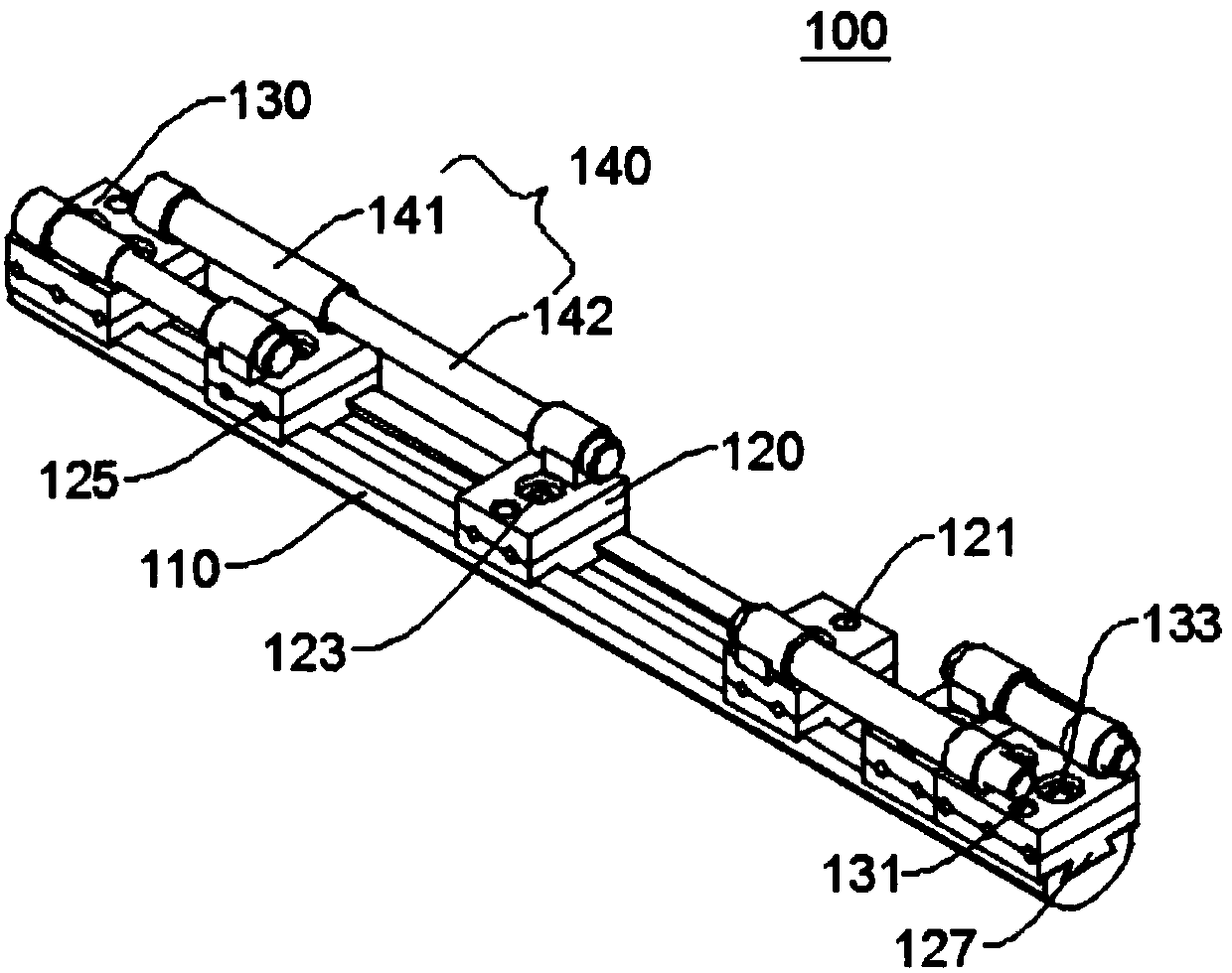
[0045]figure 1 It is a schematic view from a first angle of view of the overall structure of the single-arm external fixator 100 provided by the first embodiment of the present invention, figure 2 For a schematic diagram of the second perspective of the overall structure of the single-arm external fixator 100 provided in the first embodiment of the present invention, please refer to figure 1 with figure 2 .

[0046] This embodiment provides a single-arm external fixator 100 . The single-arm external fixator 100 includes a sliding bar 110 , a plurality of sliding blocks 120 and a plurality of extension rods 140 . The number of sliders 120 depends on the patient's condition, and can be one to four. Preferably, four sliders 120 and four extension rods 140 are used in this embodiment.

[0047] Two ends of the slide bar 110 are respectively provided with a fixed block 130 , and four slide blocks 120 are respectively connected to the slide bar 110 and located between the two fi...

no. 2 example

[0077] Another single-arm external fixator 100 provided in this embodiment includes a sliding rod 110 , four sliding blocks 120 and four extension rods 140 .

[0078] Two ends of the sliding bar 110 are respectively provided with a fixing block 130 , and the four sliding blocks 120 are respectively connected with the sliding bar 110 and located between the two fixing blocks 130 .

[0079] Two extension rods 140 are connected to each fixing block 130 ; one end of each extension rod 140 is connected to the fixing block 130 , and the other end of each extension rod 140 is fixedly connected to a sliding block 120 respectively.

[0080] Both sides of the slider 120 and the fixing block 130 are provided with bone needle holes 125 , the slider 120 slides along the slide rod 110 , and the length of the extension rod 140 can be adjusted to change the position of the bone needle holes 125 .

[0081] Specifically, a rack is provided on the slide bar 110, and a gear is provided on the sli...


PUM

PropertyMeasurementUnit
Lengthaaaaaaaaaa
Lengthaaaaaaaaaa

Abstract

The invention relates to the technical field of medical instruments, and provides to a single arm outer fixation frame. The single arm outer fixation frame comprises a sliding rod, sliding blocks andextending rods; fixing blocks are arranged at the two ends of the sliding rod respectively, and the sliding blocks are in slide connection with the sliding rod and located between the two fixing blocks; one extending rod is connected to each fixing block, one end of each extending rod is connected with the corresponding fixing block, and the other end of each extending rod is fixedly connected with one sliding block. Bone spicule holes are formed in the two sides of the sliding blocks and the two sides of the fixing blocks, the sliding blocks slide along the sliding rod, and the length of theextending rods can be adjusted to change the position of the bone spicule holes. According to the single arm outer fixation frame, the bone spicule position can be adjusted flexibly, and adjustment quantity is more accurate, which is beneficial for promoting bone growth and union in bone loss treatment.

Description

technical field [0001] The invention relates to the technical field of medical devices, in particular to a single-arm external fixator. Background technique [0002] The single-arm external fixator is used in the treatment of bone defects to fix the position of the bone. [0003] At present, when a single-arm orbital external fixator is used clinically for the treatment of bone defects, the transmission distance of the lateral mass of the external fixator is limited to a certain extent. Moreover, due to the setting of its structure, the lengths of the two lateral masses are 6.8 cm and 5.8 cm, respectively, so that it cannot give full play to the maximum space advantage of the external fixator in the treatment of bone defects and prolong the treatment time. [0004] In view of this, a single-arm external fixator is designed and manufactured, which can flexibly adjust the position between the bone needles, adapt to the growth and healing of bones, and is easy to adjust and hi...

Claims


Application Information

Patent Timeline
IPC IPC(8): A61B17/66
CPCA61B17/6441A61B17/66
Inventor 艾合买提江·玉素甫伊力扎提·伊力哈木郭少成杨习锋曾晨光
Owner GUANGZHOU SUN SHING BIOTECH CO LTD
Why Eureka
Try Eureka