
Built-in die water circulating system

A water circulation and mold technology, which is applied in manufacturing tools, glass blowing, glass manufacturing equipment, etc., can solve the problems of slow cooling speed of glass bottle body, poor cooling effect, low thermal conductivity of iron, etc., to achieve uniform cooling without dead ends, Simple structure and large cooling area

Pending Publication Date: 2018-03-09
DANYANG SHUANGFENG GLASS
View PDF3 Cites 3 Cited by
  • Summary
  • Abstract
  • Description
  • Claims
  • Application Information

AI Technical Summary

Problems solved by technology

[0002] Cooling is required when the glass bottle is heated and shaped. The cooling of the mold is one of the key factors affecting the products of this type of material. At present, the glass bottle is generally cooled separately after the mold is shaped, and the cooling method is mostly used. In blowing cooling and natural cooling, the cooling speed of the glass bottle is slower and the cooling effect is poorer in this way
However, the existing water channel is installed inside the mold for water cooling, but the material of the mold is mostly iron material, and the thermal conductivity of iron is low. Therefore, even if the water channel is installed outside, the heat is wrapped inside by the iron material. cannot escape, resulting in poor cooling, and such molds need to be dropped to very low temperatures

Method used


Image

  • Built-in die water circulating system

Examples


Embodiment Construction

[0020] In order to deepen the understanding of the present invention, the present invention will be described in further detail below in conjunction with the accompanying drawings and embodiments, which are only used to explain the present invention and do not limit the protection scope of the present invention.

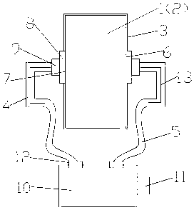
[0021] As shown in the figure, a mold built-in water circulation system includes a mold body and a built-in water circulation system. The mold body includes two mold cavities, a left mold cavity 1 and a right mold cavity 2, which are opposite to each other, and the mold cavity is empty. Cavity, the outside of the mold cavity is provided with a heat conduction layer 3, and the built-in water circulation system includes 4 metal water pipes 4 and 4 rubber hoses 5 corresponding thereto. The left and right sides of the mold cavity are respectively provided with a water inlet 6 and a water outlet 7, and the water inlet 6 and the water outlet 7 are respectively connected to ...


PUM


Abstract

Disclosed is a built-in die water circulating system. The built-in die water circulating system comprises a die body and a built-in water circulating system, wherein the die body is composed of a leftdie cavity and a right die cavity which are arranged opposite to each other, and the die cavities are hollow, and a thermal conducting layer is formed outside the die cavities; the built-in water circulating system comprises a plurality of metal water pipes and a plurality of rubber hoses; the left and the right of each die cavity are provided with a water inlet and a water outlet respectively which are connected with the corresponding metal water pipes; one end of every metal water pipe is connected with the corresponding rubber hose which is connected with a water tank; the water tank controls a water source by connecting with an electromagnetic valve, and equalizing valves are arranged between the water tank and the rubber hoses. By means of a water cooling manner, the built-in die water circulating system can absorb a large amount of heat through the latent heat of water to achieve rapid cooling of the die; the built-in die water circulating system can once cool down a product when the product is formed to improve the quality of the product; the thermal conducting layer facilitates dissipation of heat of the die cavities to achieve better cooling effects.

Description

technical field [0001] The invention relates to the field of moulds, in particular to a mold built-in water circulation system. Background technique [0002] Cooling is required when the glass bottle is heated and shaped. The cooling of the mold is one of the key factors affecting the products of this type of material. At present, the glass bottle is generally cooled separately after the mold is shaped, and the cooling method is mostly used. In the blowing cooling and natural cooling, the cooling speed of the glass bottle is slower in this way, and the cooling effect is poor. However, the existing water channel is installed inside the mold for water cooling, but the material of the mold is mostly iron material, and the thermal conductivity of iron is low. Therefore, even if the water channel is installed outside, the heat is wrapped inside by the iron material. cannot escape, resulting in poor cooling, and such molds need to be reduced to very low temperatures [0003] tem...

Claims


Application Information

Patent Timeline
Patent Type & Authority Applications(China)
IPC IPC(8): C03B9/38
CPCC03B9/3808
Inventor 刘达平巢晓峰巢建峰
Owner DANYANG SHUANGFENG GLASS
Learn More