Special clamping equipment for double-sided pressing of plate workpieces

A technology for clamping equipment and workpieces, applied in metal processing equipment, metal processing machinery parts, clamping, etc., can solve the problem that the pressing force on both sides cannot be guaranteed to be exactly the same, the force exerted by the staff is not well controlled, and the milling groove is affected and punching effect, to achieve the effect of saving raw materials and labor costs, novel structure and ingenious design

Inactive Publication Date: 2018-03-09
TIANJIN BAOLAI PRECISION MACHINERY
View PDF0 Cites 4 Cited by
  • Summary
  • Abstract
  • Description
  • Claims
  • Application Information

AI Technical Summary

Problems solved by technology

At present, when it is processed, it is usually pressed manually with a pressure plate. Because the force applied by the staff is not easy to control, especially many workpieces are made of aluminum, when the force is too large, it is easy to scratch the surface of the workpiece and affect its use.
If the applied force is too small, the clamping will be unstable, which will affect the effect of milling and drilling
In addition, because the plate workpiece needs to be pressed on both sides at the same time, the pressing force on both sides cannot be guaranteed to be exactly the same during manual clamping, so the workpiece is easy to warp and deform, which will also affect the processing effect
Many of the above problems will eventually affect the quality of product processing, resulting in an increase in the scrap rate and increasing the production cost of the enterprise

Method used


Image

  • Special clamping equipment for double-sided pressing of plate workpieces
  • Special clamping equipment for double-sided pressing of plate workpieces
  • Special clamping equipment for double-sided pressing of plate workpieces

Examples


Embodiment Construction

[0017] The embodiments of the present invention will be described in detail below in conjunction with the accompanying drawings; it should be noted that the embodiments are illustrative, not restrictive, and cannot limit the protection scope of the present invention.

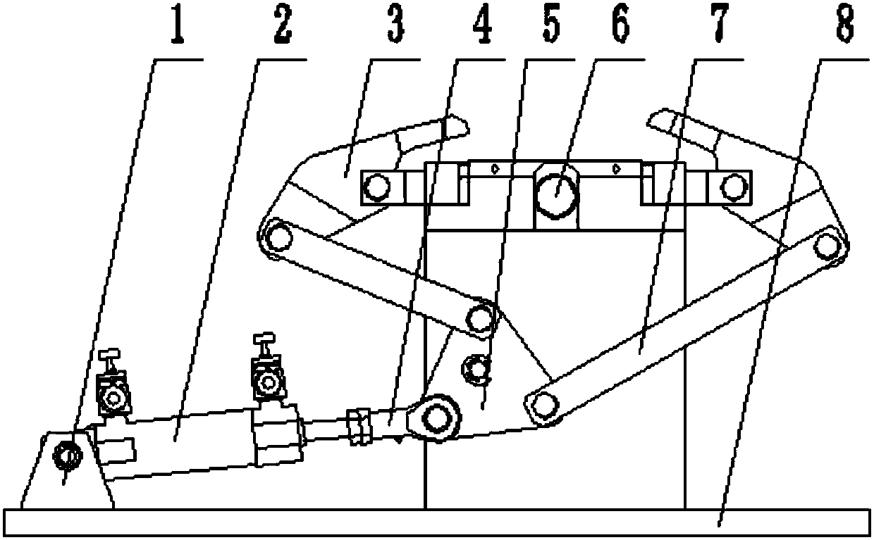
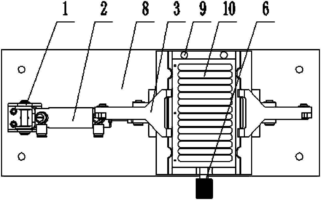
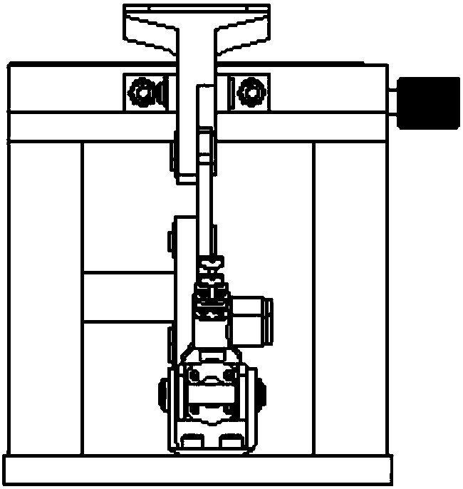
[0018] A special clamping device for double-sided pressing of plate workpieces, including a base plate 8, a support frame 11, a cylinder 2, a turntable 5, a connecting rod 7 and a pressure plate 3, and a support frame is installed on one side of the upper surface of the base plate. The front panel and the rear panel are arranged side by side, and the lower ends of the front panel and the rear panel are installed on the bottom panel, and the upper ends of the front panel and the rear panel are installed on the top panel. Make the workpiece installation area, install the vertical positioning column 9 on the rear end of the upper surface of the top plate, and the positioning column is usually two symmetrically arran...


PUM


Abstract

The invention relates to a special clamping device for double-sided pressing of plate workpieces, which includes a base plate, a support frame, a cylinder, a turntable, a connecting rod and a pressure plate. A support frame is installed on one side of the upper surface of the base plate. The back plate and the top plate are composed of a workpiece installation area on the top surface of the top plate, a vertical positioning column is installed on the rear end of the top plate surface, and a horizontal top wire is installed on the front surface of the top plate; a hinge is installed on the other side of the bottom plate surface A cylinder is installed on the hinge seat, and the cylinder is connected with an active push rod. The upper ends of the two connecting rods are hinged with a pressing plate, and the two pressing plates are respectively located above the left and right sides of the top plate. The invention is a special clamping device for double-sided pressing of plate workpieces with a high degree of automation. Using the device can increase the clamping speed, ensure the processing quality, improve the product qualification rate, and save the raw material and labor costs of the enterprise.

Description

technical field [0001] The invention relates to a clamping fixture in the technical field of machining, in particular to a special clamping device for double-sided pressing of a plate workpiece. Background technique [0002] Plate workpieces are widely used in electronic instruments or other industries, and the surface of many plate parts needs to be milled and drilled, such as heat sinks. At present, when processing it, it is usually pressed manually with a pressure plate. Since the force applied by the staff is not easy to control, especially many workpieces are made of aluminum, when the force is too large, it is easy to scratch the surface of the workpiece and affect its use. If the applied force is too small, the clamping will not be stable, which will affect the effect of milling and drilling. In addition, because the plate workpiece needs to be pressed on both sides at the same time, the pressing force on both sides cannot be guaranteed to be exactly the same during ...

Claims


Application Information

Patent Timeline
IPC IPC(8): B23Q3/08
CPCB23Q3/082
Inventor 崔雅臣李绍功崔文来李绍德崔建涛崔超崔越
Owner TIANJIN BAOLAI PRECISION MACHINERY
Why Eureka
Try Eureka