
Arbitrary polarization wide beam patch antenna

A patch antenna and wide beam technology, which is applied in the field of microwave and millimeter wave passive devices, can solve the problems of unsatisfactory antenna beam broadening and large radiation in the second half, and achieve the effect of compact structure, widening beam width and reducing interference

Pending Publication Date: 2018-03-06
成都瑞德星无线技术有限公司
View PDF12 Cites 7 Cited by
  • Summary
  • Abstract
  • Description
  • Claims
  • Application Information

AI Technical Summary

Problems solved by technology

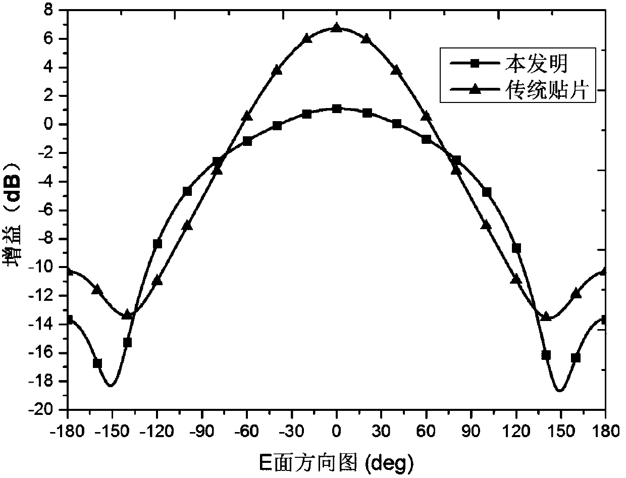
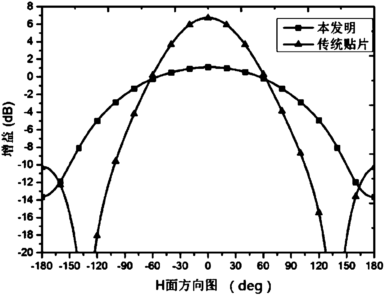
The antenna uses a microstrip vibrator as a director, so that the beam at the bottom elevation angle has end-fire characteristics and broadens the beam. However, the beam broadening of this antenna is not ideal and only has a width of 100°, and it also only works in circular polarization. The second half of the radiation is large, etc.

Method used


Image

  • Arbitrary polarization wide beam patch antenna
  • Arbitrary polarization wide beam patch antenna
  • Arbitrary polarization wide beam patch antenna

Examples


Embodiment Construction

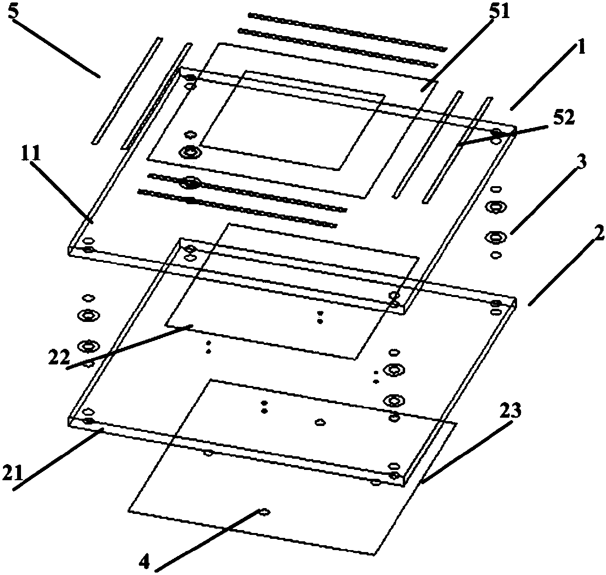
[0018] The present invention will be further described below in conjunction with accompanying drawing and specific embodiment: figure 1 As shown, a wide-beam patch antenna with arbitrary polarization includes a first circuit board 1, a second circuit board 2, four plastic studs 3 and four feeding ports 4; it is characterized in that: the first circuit board 1 It includes a first dielectric substrate 11 and a metal composite structure 5 printed on the upper surface of the first dielectric substrate 1; the second circuit board 2 includes a second dielectric substrate 21, a radiation patch 22 printed on the upper surface of the second dielectric substrate 21, and a printed On the square metal floor 23 on the lower surface of the second dielectric substrate 21, both dielectric substrates are F4B high-frequency boards with a thickness of 2mm; the first circuit board 1 and the second circuit board 2 pass through four equal-length plastic screws. The columns 3 are aligned and stacked...


PUM


Abstract

The invention discloses an arbitrary polarization wide beam patch antenna including a first circuit board and a second circuit board. The first circuit board includes a square metal ring and eight parasitic metal wires. The second circuit board includes a square metal ground board, a radiation paster and four plastic bolts. The antenna provided by the invention can be applied to a satellite communication system and can also be used as an array element of a phase control array antenna. The antenna provided by the invention has advantages of being capable of an arbitrary polarization mode when having the wide beam characteristic; having a low back lobe electric level at the same time; and being simple in structure.

Description

technical field [0001] The invention belongs to the technical field of microwave and millimeter wave passive devices, in particular to a wide beam antenna in microwave and millimeter wave passive devices. Background technique [0002] Patch antenna is a commonly used antenna form in modern wireless communication systems. Because of its low profile, stable performance, easy integration, and low cost, it is widely used in miniaturized receiving terminals, phased array radars, and communication satellites. . In these applications, patch antennas are required to have wide beam characteristics, but the typical 3dB beamwidth of patch antennas is about 90°, which cannot meet the requirements of some applications. For phased array antennas, the beam width of the array elements will directly affect the size of the scanning range. At the same time, in navigation satellite terminal systems such as Beidou / GPS, antennas are required to have hemispherical coverage capabilities, and trad...

Claims


Application Information

Patent Timeline
Patent Type & Authority Applications(China)
IPC IPC(8): H01Q9/04H01Q1/38H01Q1/48H01Q1/50H01Q21/24
Inventor 林先其杨永穆王豹庞平李立江黄登祥张廷钎袁图友
Owner 成都瑞德星无线技术有限公司
Learn More