Device and method for testing friction and wear of falling tower ring block
A friction and wear test, drop tower technology, applied in measuring devices, testing wear resistance, instruments, etc., can solve the problems of inability to solve the problem of three-dimensional motion ground simulation of complex trajectories, limited research scope, and unsatisfactory effectiveness. Simple structure, strong impact resistance and stable structure
- Summary
- Abstract
- Description
- Claims
- Application Information
AI Technical Summary
Problems solved by technology
Method used
Image
Examples
Embodiment 1
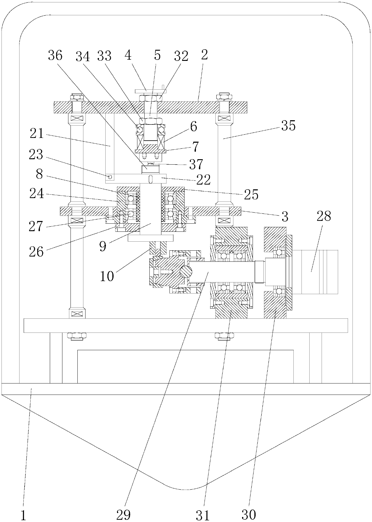
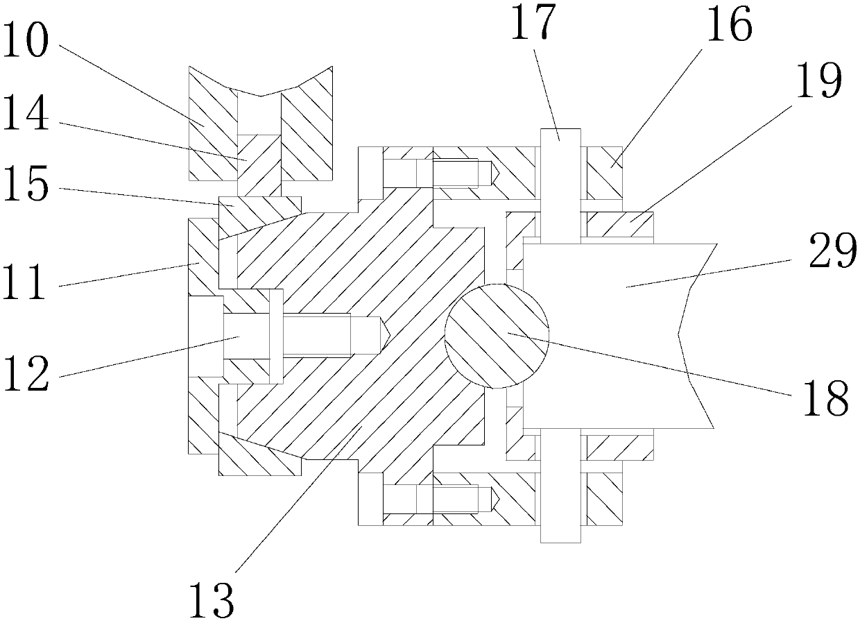
[0045] A drop tower ring block friction and wear test device, including a frame, a load loading mechanism, a block sample clamping mechanism, a ring sample clamping mechanism and a friction power device;
[0046] The frame is fixedly arranged in the drop cabin of the drop tower, and the frame has a first support plate, a second support plate and a power device fixing seat for installing the friction power device, and the first support plate and the second support plate are arranged up and down respectively;
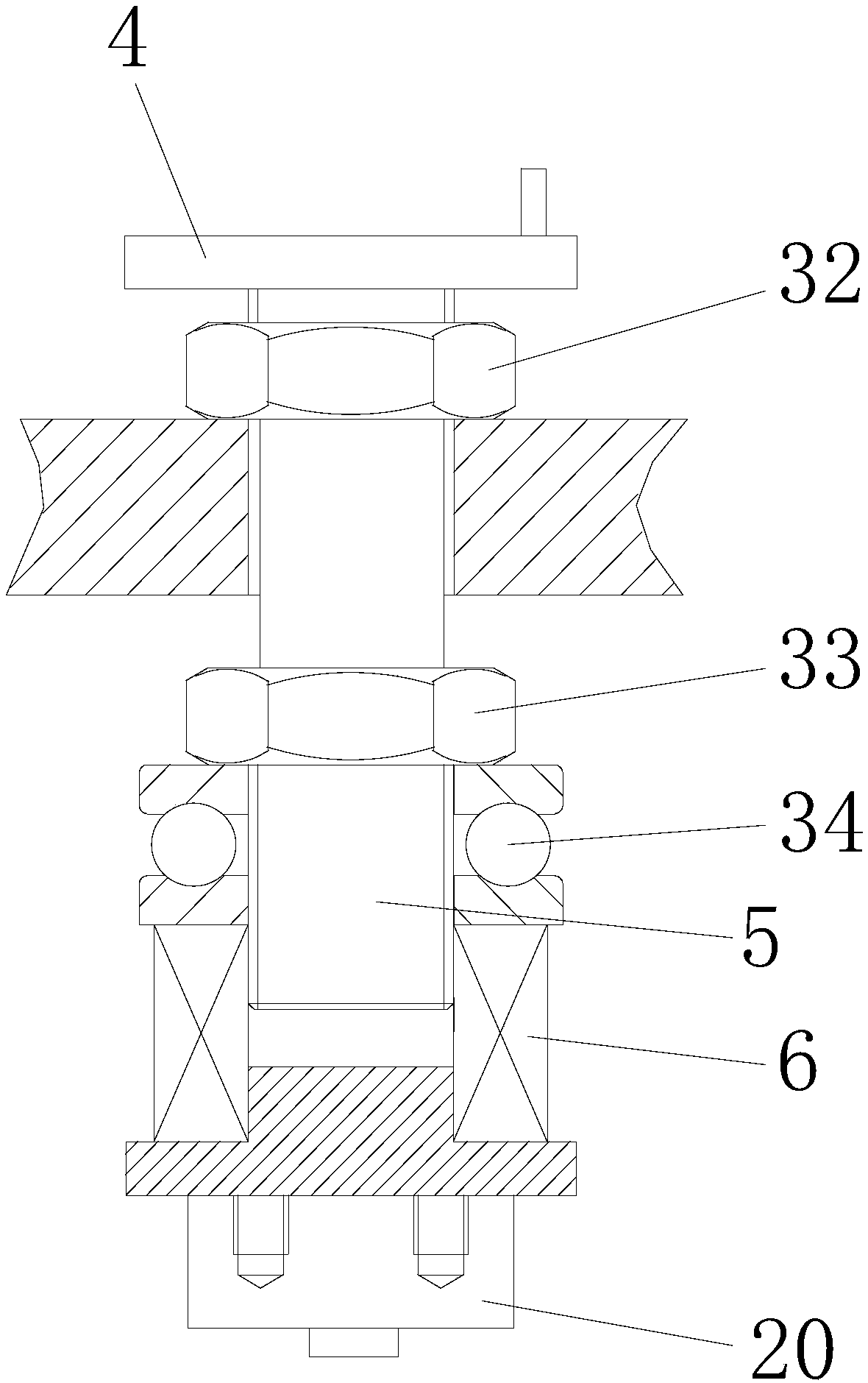
[0047] The load loading mechanism includes a loading handwheel, a loading screw, a spring pushing mechanism, a loading spring, and a spring mounting seat. The loading handwheel is connected to the loading screw to drive the loading screw to rotate. A threaded through hole is opened on the first support plate for loading The screw rod passes through the threaded through hole of the first support plate, the thread on the outer surface of the loading screw is connected with t...
Embodiment 2
[0060] The difference between this embodiment and Embodiment 1 is that it also includes a friction detection mechanism. The friction detection mechanism includes a baffle plate, a transmission plate and a friction sensor, the baffle plate is fixedly arranged, the transmission plate is fixedly connected with the transmission shaft, and the block sample The mounting seat is installed on the bottom end surface of the transmission shaft. The center of the sample mounting seat is staggered from the shaft center of the transmission shaft. at the contact position.
[0061] Here, the friction sensor is installed on the baffle plate as an example: During the test, the transmission shaft rotates to drive the drive plate to rotate toward the baffle plate, so that the drive plate contacts the friction sensor. After the two are in contact, the friction sensor can Detect the torque generated by the transmission shaft during the test, and convert the measured torque into the corresponding fr...
Embodiment 3
[0063] The difference in this embodiment is that the block sample clamping mechanism also includes a clamping mechanism bearing seat, an upper seat baffle plate, a lower seat baffle plate and a bushing bearing, the clamping mechanism bearing seat is fixedly installed in the mounting hole, and the bushing bearing Set in the bearing seat of the clamping mechanism, the upper baffle and the lower baffle are respectively arranged on the upper opening and the lower opening of the bearing pedestal of the clamping mechanism, the guide bush is installed in the bushing bearing, and the transmission shaft passes through the upper baffle, Guide bushing and lower seat baffle.
PUM
 Abstract
Description
Claims
Application Information
 - R&D
- Intellectual Property
- Life Sciences
- Materials
- Tech Scout
- Unparalleled Data Quality
- Higher Quality Content
- 60% Fewer Hallucinations
Browse by: Latest US Patents, China's latest patents, Technical Efficacy Thesaurus, Application Domain, Technology Topic, Popular Technical Reports.
© 2025 PatSnap. All rights reserved.Legal|Privacy policy|Modern Slavery Act Transparency Statement|Sitemap|About US| Contact US: help@patsnap.com


