
A new self-skimming type current-limiting constant-flow valve

A constant flow valve, a new type of technology, applied in the direction of balance valve, valve device, valve details, etc., can solve the problems of toxic and harmful substances discharge, environmental pollution, reducing sewage treatment capacity and so on

Active Publication Date: 2019-06-14
陈银周
View PDF6 Cites 0 Cited by
  • Summary
  • Abstract
  • Description
  • Claims
  • Application Information

AI Technical Summary

Problems solved by technology

[0003] In addition, when heavy rain occurs, a large amount of runoff rainwater flows to the urban sewage pipes through the rainwater wells and sewage interception wells, and then enters the sewage treatment plant, which puts the sewage treatment plant in a serious overload operation state, greatly reduces the sewage treatment capacity, and discharges toxic and harmful substances. water bodies, causing serious environmental pollution

Method used


Image

  • A new self-skimming type current-limiting constant-flow valve
  • A new self-skimming type current-limiting constant-flow valve
  • A new self-skimming type current-limiting constant-flow valve

Examples


Embodiment Construction

[0021] The specific embodiments of the present invention will be described in further detail below in conjunction with the drawings and embodiments. The following examples are used to illustrate the present invention, but not to limit the scope of the present invention.

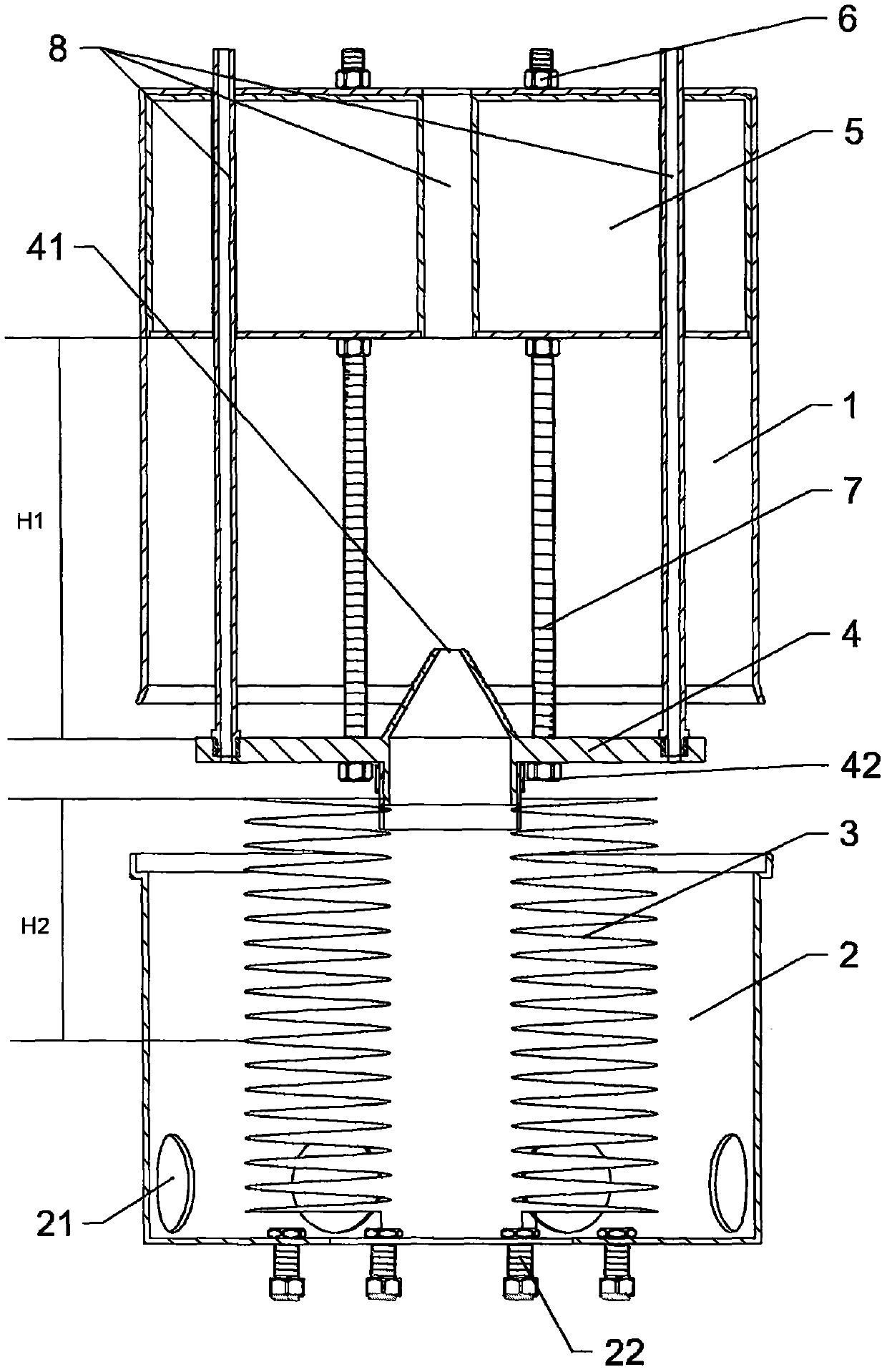
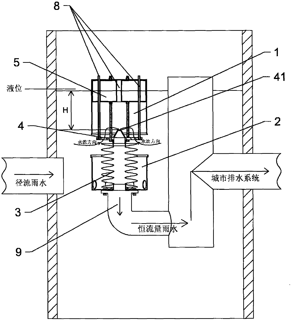
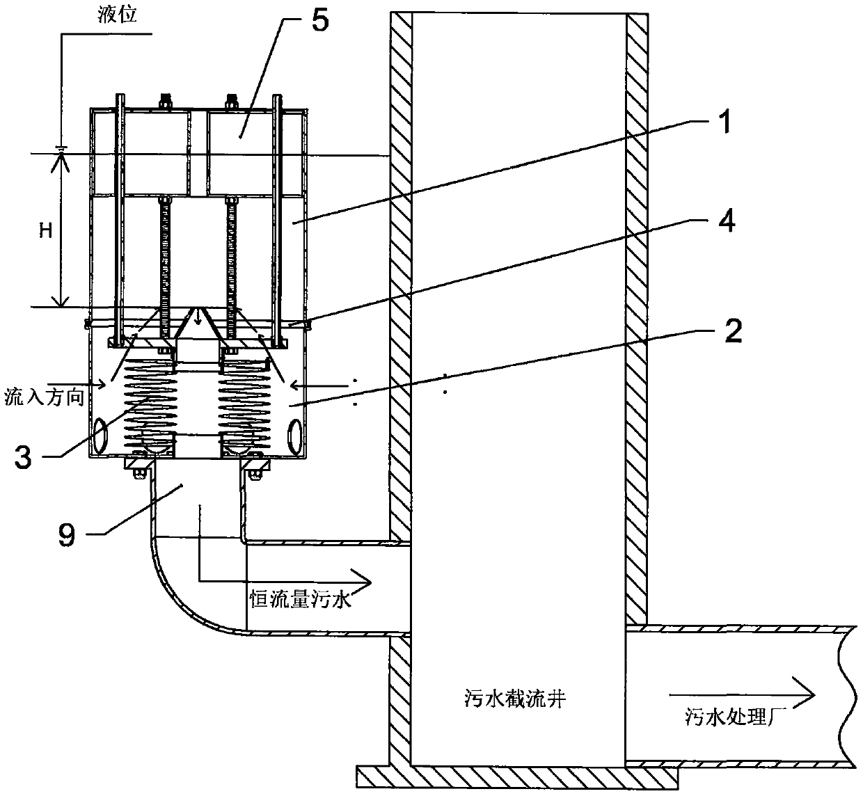
[0022] Such as figure 1 and figure 2 As shown, a new type of self-skimming current-limiting and constant-flow valve is matched and connected with a drain pipe 9. It includes a valve body 1 and a valve seat 2, and also includes a bellows 3, a restrictive orifice plate 4, a float 5 and a ventilation pipe 8. , The pontoon 5 is opened and fixed on the upper part of the valve body 1, the flow limiting orifice plate 4 is fixed below the pontoon 5 by bolts 6 that vertically pass through the pontoon 5, between the flow limiting orifice plate 4 and the pontoon 5 The distance is adjustable and can be locked by the nut 7 on the bolt 6. One end of the ventilation pipe 8 penetrates through the limiting flow orifice plate 4,...


PUM


Abstract

The invention discloses a novel self-skimming type flow-limiting constant-flow valve matched and connected with a water drainage pipe. The novel self-skimming type flow-limiting constant-flow valve comprises a valve body and a valve seat and further comprises a corrugated pipe, a flow limiting hole plate, a buoy and ventilation ducts. The buoy is arranged on and fixed to the upper portion in the valve body. The limiting hole plate is fixed to the lower portion of the buoy through bolts. The distance between the flow limiting hole plate and the buoy can be locked through nuts. One end of each ventilation duct penetrates the flow limiting hole plate, and the other end of each ventilation duct penetrates the buoy. A water inlet hole penetrating the upper surface and the lower surface of the flow limiting hole plate is formed in the flow limiting hole plate. An opening of the water inlet hole is located below the liquid level all the time. The corrugated pipe is arranged below the flow limiting hole plate, and one end of the corrugated pipe and the water inlet hole communicate with each other. The corrugated pipe has the function that the corrugated pipe is freely stretched out and drawn back along with rising and falling of the buoy, the stretch-out and draw-back height is kept consistent with the rising and falling height of the liquid level, and the other end of the corrugated pipe is fixed to the water drainage pipe through the valve seat. The invention provides the novel self-skimming type flow-limiting constant-flow valve which replaces a traditional overflow weir, effectively solves city flood and can improve the sewage treatment capacity of a sewage treatment plant.

Description

Technical field [0001] The invention relates to the technical field of flow regulating valves, in particular to a new type of valve that can not only skim slag by itself but also keep the outlet flow constant. Background technique [0002] In recent years, many cities across the country and even in developed countries have suffered from frequent floods. Flood disasters have not only caused huge damage to the lives and properties of the people, but also caused great economic losses to the country. When a rainstorm occurs, the land runoff rainwater, roof rainwater, etc. are all converged in temporary water storage facilities such as lakes, ponds, pools, etc. These water storage facilities are filled with rainwater to drain outward by means of overflow weirs. When the overflow water is discharged to the receiving water body and the urban drainage system at the same time, the receiving water body and the urban drainage system will eventually be overloaded and there is no time to disc...

Claims


Application Information

Patent Timeline
Patent Type & Authority Patents(China)
IPC IPC(8): F16K17/20F16K31/18E03F7/02
CPCE03F7/02F16K17/20F16K31/18
Inventor 陈银周
Owner 陈银周
Learn More