
an anaerobic reactor

An anaerobic reactor and reaction zone technology, applied in the field of anaerobic reactors, can solve problems such as insufficient construction space, large energy consumption, and limited diameter, and achieve the effects of improving volume utilization, uniform water distribution, and avoiding local acidification

Inactive Publication Date: 2021-03-09
QINGDAO TECHNOLOGICAL UNIVERSITY
View PDF15 Cites 0 Cited by
  • Summary
  • Abstract
  • Description
  • Claims
  • Application Information

AI Technical Summary

Problems solved by technology

[0002] Three-phase separators are mostly used in upflow anaerobic sludge bed reactors (UASB) in biological sewage treatment to separate digested gas, digested liquid and sludge particles. The digested gas is exported from the top of the reactor, and the sludge particles slide down automatically. It settles to the sludge bed at the bottom of the reactor, and the digested liquid is discharged from the clarification zone; the three-phase separator can collect the biogas generated from the reaction chamber under the separator, so that the suspended matter above the separator settles down; because the aerobic organism Treatment requires a large amount of aeration and high energy consumption, so it is inevitable to seek technologies with low energy consumption and high sewage treatment rate, and anaerobic biological treatment technologies that can generate biogas and other energy that can be used directly come into being. At present, anaerobic reaction The research direction and focus of the reactor have four points: one is to improve the influent water quality, pretreatment or introduce bacteria, the other is to determine the structure of the reactor under the condition of high hydraulic load from the perspective of hydraulic mass transfer dynamics, and improve the treatment efficiency. The third is the full realization of the three-stage four-flora theory, and the fourth is the research on the water distribution structure and the three-phase separator; for an anaerobic reactor with small water volume, due to the limited diameter, a certain height is often required to install the three-phase separator, and the gas Both the chamber and the precipitation area need space, and the construction space is insufficient

Method used


Image

  • an anaerobic reactor

Examples


Embodiment 1

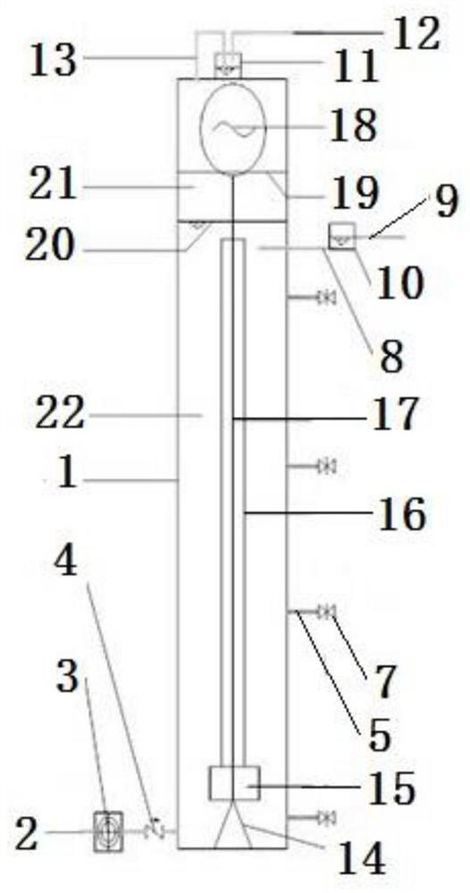
[0013]The main structure of the anaerobic reactor involved in this embodiment includes a tank body 1, an inlet pipe 2, an inlet pump 3, a check valve 4, a mud discharge horizontal pipe 5, a valve 7, an outlet pipe 8, a drain pipe 9, a positioning water seal 10. Constant pressure water seal 11, air outlet pipe 12, air pipe 13, bottom support 14, diffusion pump 15, water suction pipe 16, bearing 17, motor 18, top support 19, liquid level 20, air chamber 21 and reaction zone 22; A water inlet pipe 2 of a tubular structure is arranged on the outside of the bottom of the tank body 1 of the hollow cylindrical structure, and a water inlet pump 3 of a horizontal structure is arranged on the end of the water inlet pipe 2 far away from the tank body 1, and the water inlet pipe 2 close to the tank body 1 One end is provided with a check valve 4, and the outside of the middle and lower part of the tank body 1 is provided with 4-6 segments of mud discharge horizontal pipes 5 in a tubular st...


PUM


Abstract

The invention belongs to the technical field of biochemical sewage treatment equipment, and particularly relates to an anaerobic reactor. A main body structure comprises a tank body, a water inlet pipe, a water inlet pump, a check valve, a sludge discharging transverse pipe, a valve, a water outlet pipe, a drain pipe, a positioning water seal, a constant-pressure water seal, a gas outlet pipe, a gas pipe, a bottom support, a diffusion pump, a water suction pipe, a bearing, a motor, a top support, a liquid level, a gas chamber and a reaction zone. A circulating stirring unit is used for achieving uniform water distribution; a hydraulic gradient and an aerodynamic force are used for promoting the growth of granular sludge and diffusion of microbubbles; a sealed tank body is used, and an internal circulating stirring unit which operates intermittently is arranged inside the tank body; after water enters, the internal circulating stirring unit sucks liquid, scum and gas on the liquid levelwhich are secondarily distributed at the bottom of the tank body, and gas produced in the reaction process floats quickly into the gas chamber under a mechanical action and is drained at any time through the constant-pressure water seal; the anaerobic reactor performs degassing in a stirring period under a full sealing condition, and performs sludge-water separation in a non- stirring period, sothat a three-phase separation effect is achieved.

Description

Technical field: [0001] The invention belongs to the technical field of sewage biochemical treatment equipment, and specifically relates to an anaerobic reactor, which uses pneumatic, hydraulic gradient and mass transfer to enhance the activity of granular sludge, eliminates floating mud on the liquid surface through mechanical internal circulation, strengthens the release of air bubbles, and improves The three-phase separation performance and the equivalent displacement capacity of static separation can realize the efficient separation of mud, water and gas, and are suitable for anaerobic treatment of small flow and high concentration sewage. Background technique: [0002] Three-phase separators are mostly used in upflow anaerobic sludge bed reactors (UASB) in biological sewage treatment to separate digested gas, digested liquid and sludge particles. The digested gas is exported from the top of the reactor, and the sludge particles slide down automatically. It settles to th...

Claims


Application Information

Patent Timeline
Patent Type & Authority Patents(China)
IPC IPC(8): C02F3/28
CPCC02F3/28
Inventor 管锡珺
Owner QINGDAO TECHNOLOGICAL UNIVERSITY
Learn More