Aligning device

A technology of supporting frame and roller frame, which is applied in the field of adjusters, can solve the problems that the adjuster cannot display the working status of the adjuster in time, and achieve the effects of saving labor, ensuring production safety, and reasonable structural design

Inactive Publication Date: 2018-03-06
李云峰
View PDF0 Cites 0 Cited by
  • Summary
  • Abstract
  • Description
  • Claims
  • Application Information

AI Technical Summary

Problems solved by technology

[0002] The hydraulic adjuster is mainly used on the conveying parts of the production line. When the belt deviates, it contacts the inspection drive wheel, so that the inspection drive wheel rotates and drives the oil pump to work, so that the piston cylinder reciprocates, adjusts the direction of the roller line, and moves with the belt. The direction forms a certain angle, and the friction force is used to make the belt run in the correct direction, avoiding problems such as loose material, shutdown, and belt tearing caused by belt deviation. The existing adjuster cannot display the working status of the adjuster in time.

Method used


Image

  • Aligning device

Examples


Embodiment Construction

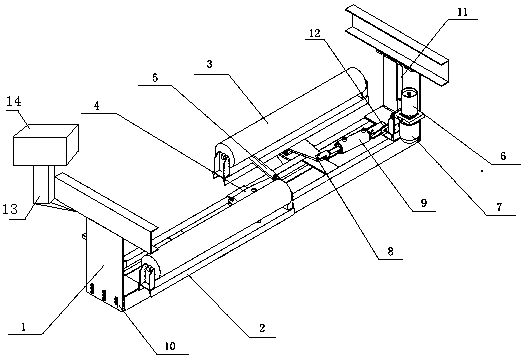
[0010] The present invention will be described in further detail below in conjunction with the accompanying drawings.

[0011] The invention discloses an adjustment device, which is provided with a supporting frame 1, two adjusting roller frames 2 are arranged symmetrically on the supporting frame 1, rollers 3 are arranged on the adjusting roller frames 2, and conversion supports are arranged between the adjusting roller frames 2 The frame 4 and the adjustment roller frame 2 are provided with a balance arm 5, the balance arm 5 is connected to the conversion support frame 4 and is in a movable connection state, and one end of the support frame 1 is provided with a drive inspection device, and the adjustment roller frame 2 on the side close to the detection drive device A driving force arm 8 is provided, and a movable state is connected between the detection drive device and the driving force arm 8 through a piston cylinder 9; a height adjusting bolt 10 is provided on the support...


PUM


Abstract

The invention discloses an adjustment device, which is provided with a support frame (1), two adjustment roller frames (2) are arranged symmetrically on the support frame (1), and rollers (3) are arranged on the adjustment roller frame (2). A conversion support frame (4) is provided between the adjustment roller frames (2), and a balance arm (5) is provided on the adjustment roller frame (2), and the balance arm (5) is connected with the conversion support frame (4) and is movably connected state, one end of the support frame (1) is equipped with a drive detection device, and the adjustment roller frame (2) near the detection drive device is provided with a driving force arm (8), and the piston cylinder is passed between the detection drive device and the driving force arm (8). (9) The connection is movable; the support frame (1) is provided with height adjustment bolts (10); the support frame (1) is provided with a connecting steel frame (13), and the connecting steel frame (13) is provided with a controller ( 14). The invention has a reasonable structural design, can intuitively display the working state of the adjuster, saves labor, and ensures production safety.

Description

technical field [0001] The invention discloses a rectifier, in particular to a rectifying device. Background technique [0002] The hydraulic adjuster is mainly used on the conveying parts of the production line. When the belt deviates, it contacts the inspection drive wheel, so that the inspection drive wheel rotates and drives the oil pump to work, so that the piston cylinder reciprocates, adjusts the direction of the roller line, and moves with the belt. The direction forms a certain included angle, and the friction force is used to make the belt run in the correct direction, avoiding problems such as loose material, machine stoppage, and belt tearing caused by belt deviation. The existing adjuster cannot display the working status of the adjuster in time. Contents of the invention [0003] The technical problem to be solved by the present invention is to provide an adjustment device that can display the working status in time. [0004] In order to solve the above-ment...

Claims


Application Information

Patent Timeline
IPC IPC(8): B65G39/16
CPCB65G39/16
Inventor 李云峰
Owner 李云峰
Why Eureka
Try Eureka