Eureka AIR delivers breakthrough ideas for toughest innovation challenges, trusted by R&D personnel around the world.

Multi-frequency resistivity exploration method

A technology of resistivity and apparent resistivity, which is applied in the field of electrical prospecting, can solve the problems of improving the efficiency of exploration work, unable to convert resistivity data, and unable to obtain the resistivity characteristics reflecting the exploration area.

Active Publication Date: 2018-03-02
CENT SOUTH UNIV
View PDF4 Cites 19 Cited by
  • Summary
  • Abstract
  • Description
  • Claims
  • Application Information

AI Technical Summary

Problems solved by technology

However, there are some problems in this patent: 1) When a plurality of different power supply electrodes supply power at the same time, it is impossible to judge which or which two current signals of the power supply electrodes contribute to the potential difference data obtained on the measurement electrodes, because the potential difference data obtained on the measurement electrodes The potential difference data is the potential response provided by all power supply electrodes, so it is impossible to convert the resistivity data at different exploration depths, so the obtained potential difference data cannot obtain the resistivity characteristics reflecting the different depths of the exploration area, and it is also impossible to obtain the data of the exploration area. Geological features; 2) This patent requires the use of multiple sets of sending units, thereby increasing the complexity and number of equipment, which is not conducive to improving the efficiency of exploration work, and also increases the cost and difficulty of exploration

Method used


Image

  • Multi-frequency resistivity exploration method
  • Multi-frequency resistivity exploration method

Examples


Embodiment Construction

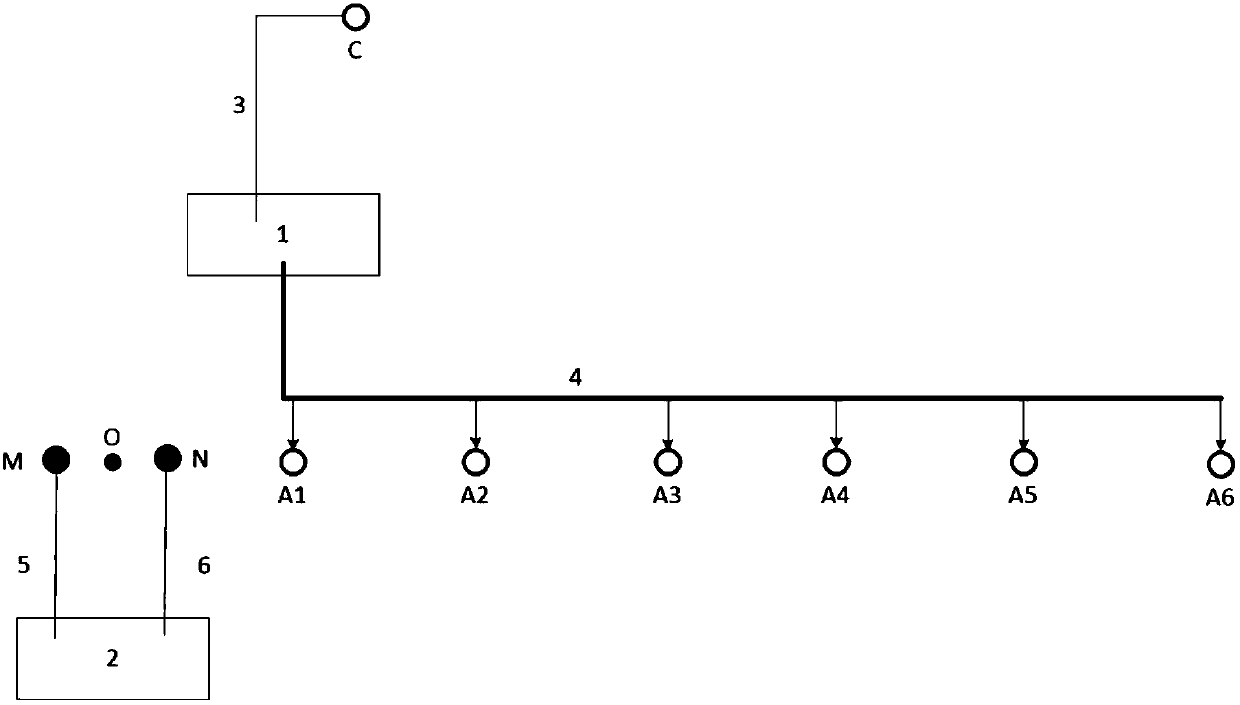
[0018] In order to make the technical problems, technical solutions and beneficial effects solved by the present invention clearer, the following in conjunction with the appended figure 1 , attached figure 2 and specific implementation methods, the present invention will be described in further detail.

[0019] If to obtain the resistivity distribution characteristics of a measuring point O from shallow to deep, it is necessary to arrange power supply electrodes at six positions, then the method proposed by the present invention can be implemented according to the following steps:

[0020] a) Arrange six power supply electrodes (A 1 ,A 2 ,A 3 ,A 4 ,A 5 ,A 6 ) and an infinite power supply electrode C, and connected to the infinite power supply electrode C and can simultaneously transmit six frequencies (0.1, 0.2, 0.4, Hertz) wire 3 of the electrical transmitter 1, connected to six power supply electrodes (A 1 ,A 2 ,A 3 ,A 4 ,A 5 ,A 6 ) and the six-core wire 4...


PUM


Abstract

The invention provides a multi-frequency resistivity exploration method. The method comprises the steps of 1) transmitting current signals with different frequencies through n grounded power supply electrodes and an infinity power supply electrode by adopting an electrical transmitter capable of transmitting n mutually independent current signals with different frequency values; 2) acquiring n electric field total signals with different frequencies between two grounded measurement electrodes through an electrical receiver in a target area to be measured, separating the electric field total signals with different frequencies to obtain potential different data of n frequencies; 3) acquiring three-dimensional coordinates of the positions of the power supply electrodes and the measurement electrodes; 4) performing conversion between the potential difference data of the different frequencies and apparent resistivity data based on an apparent resistivity algorithm of electrical exploration;6) performing inversion processing on all of the apparent resistivity data to obtain real resistivity distribution characteristics of the target area to be measured; and 7) analyzing geological characteristics of the target area to be measured based on the real resistivity distribution characteristics. The method is conducive to significantly improving the field work efficiency and the explorationeffect of electrical exploration and reducing the cost of electrical exploration.

Description

technical field [0001] The invention relates to a resistivity prospecting method in the field of electrical prospecting. Background technique [0002] The conventional apparent resistivity method is to supply power to the earth through two power supply electrodes A and B, and use two measuring electrodes M and N to receive the electric field generated by the power supply electrodes A and B and the influence of different underground resistivity media on the electric field. The potential difference formed between the electrodes and the exploration depth are related to the distance between AB or AO (point O is the midpoint of MN), the power supply strength from AB to the earth, and the sensitivity and accuracy of receiving instruments. [0003] The above method uses two power supply electrodes to supply power. In order to measure the resistivity at different depths, after each measurement of the potential difference between the measurement electrodes M and N, the positions of t...

Claims


Application Information

Patent Timeline
IPC IPC(8): G01V3/38G01V3/08
CPCG01V3/08G01V3/38
Inventor 刘春明唐冬春林荣沛赵于前刘昕程云涛
Owner CENT SOUTH UNIV
Why Eureka
Eureka Blog
Learn More