Eureka AIR delivers breakthrough ideas for toughest innovation challenges, trusted by R&D personnel around the world.

Asymmetric electrical method-based sounding method

An asymmetric and electrical technology, applied to radio wave measurement systems, measurement devices, electrical/magnetic exploration, etc., can solve the problems of reducing exploration efficiency, increasing the workload of small pole distances, and bulky power supply systems

Active Publication Date: 2017-05-10
CENT SOUTH UNIV
View PDF3 Cites 7 Cited by
  • Summary
  • Abstract
  • Description
  • Claims
  • Application Information

AI Technical Summary

Problems solved by technology

In order to achieve deep sounding, the interval coefficient is increased. With the increase of the interval coefficient, the electric field signal attenuates quickly. In order to achieve a greater exploration depth, it can only be realized by increasing the power of the power supply system, which will lead to The power supply system is bulky, reducing the exploration efficiency
[0008] The middle-ladder section sounding method borrows the middle-ladder profile mode, and achieves the purpose of sounding by changing the size of the middle-ladder power supply electrode distance. However, this method uses a symmetrical quadrupole with a small pole pitch to measure the electrical signal of each measurement point for the sounding work of the power supply point within the range of the measurement point, which results in the need to carry out two measurements for each measurement point. Although this method of electrical prospecting can reduce the workload of sounding with large polar distance, it increases the workload of small polar distance

Method used


Image

  • Asymmetric electrical method-based sounding method
  • Asymmetric electrical method-based sounding method
  • Asymmetric electrical method-based sounding method

Examples


Embodiment 1

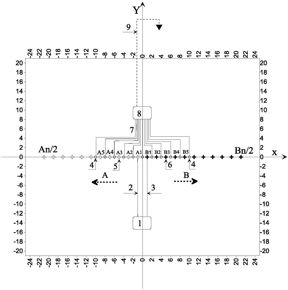
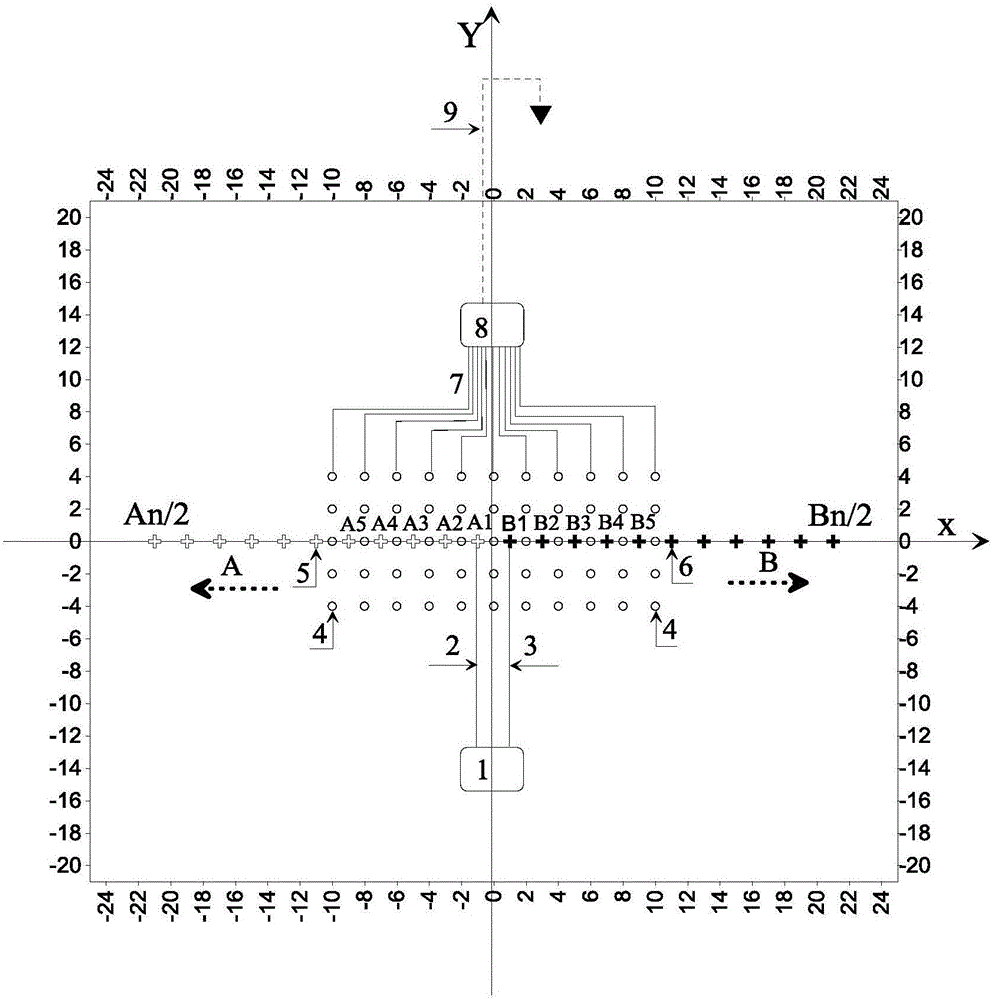
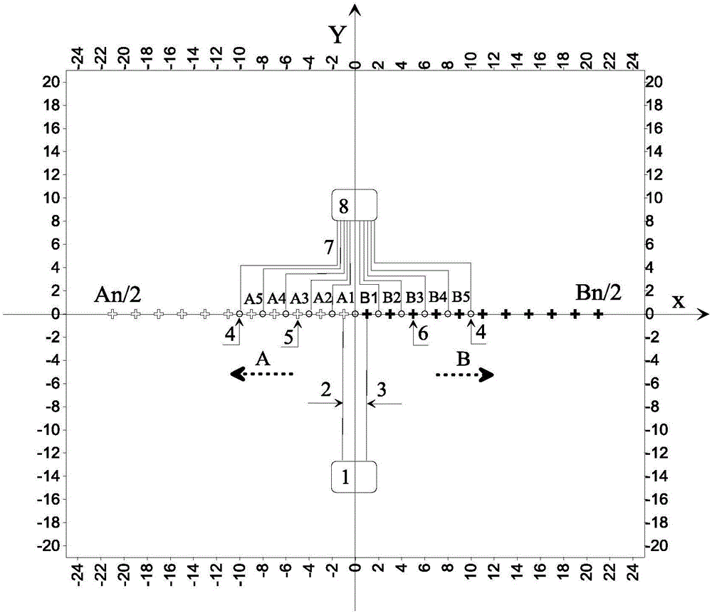
[0052] 1 in the figure is the electrical prospecting transmitter, 2 is the A pole power supply line, 3 is the B pole power supply line, the circular symbol 4 refers to the electric field signal measurement electrode point, and the hollow cross symbol 5 refers to the A pole The power supply point, the solid cross symbol indicated by 6 is the B pole power supply point, 7 is the electric field signal measurement wire, 8 is the electrical prospecting receiver, 9 is the electric field signal infinity measurement wire and electrode, A and the dashed arrow indicate the A pole The direction of the pole running of the power supply point, B and the dotted arrow indicate the direction of the pole running of the power supply point of the B pole.

[0053] The specific implementation of the method is divided into two cases of a two-dimensional asymmetric electric sounding monopole measuring device and a three-dimensional asymmetric electric sounding monopole measuring device for description ...


PUM


Abstract

An asymmetric electrical method-based sounding method is disclosed. A series of equal interval power supply points that are symmetric about only one fixed point are designed, underground power supply can be realized via two power supply points symmetric about the fixed point through an electrical method exploration transmitter, the electrical method exploration transmitter is used for simultaneously receiving electric field signals of all measurement points on an exploration line, and apparent resistivity and induced polarization parameters of each measurement point are obtained when each pair of symmetric power supply points are used for power supply. Via the method disclosed in the invention, workloads of power supply point arrangement can be greatly reduced, a plurality of sounding points can be subjected to sounding operation via a multichannel electrical method instrument or a plurality of electrical method instruments, and exploration efficiency of a two dimensional or three dimensional electrical method can be improved. In a three dimensional asymmetric electrical method sounding mode, exploration efficiency and exploration effects can be improved due to adoption of the three dimensional electrical method sounding mode.

Description

technical field [0001] The invention relates to an electrical sounding method in the field of geophysics. Background technique [0002] At present, there are symmetrical quadrupole sounding, dipole-dipole sounding and middle ladder profile sounding in two-dimensional electrical prospecting. [0003] The symmetrical quadrupole sounding method uses approximately logarithmically equidistant power supply distances at each measurement point to realize two-dimensional electrical survey sounding. The advantage of this method is that each measurement point is arranged with a symmetrical power supply electrode relative to the measurement point. The measurement electrode distance is controlled to be less than 1 / 3 of the power supply electrode distance, so that the measurement signal at the measurement point presents a horizontal field trend, and the geological interpretation is simple. However, since each measurement point needs to arrange a series of power supply points, each arrang...

Claims


Application Information

Patent Timeline
IPC IPC(8): G01V3/08
CPCG01V3/08
Inventor 刘春明龙西亭赵于前柳卓
Owner CENT SOUTH UNIV
Why Eureka
Eureka Blog
Learn More