Control method and control unit of driving circuit of electric vehicle as well as electric vehicle

A control method and technology of a control unit are applied in the control of electric vehicle drive circuits and in the field of electric vehicles, which can solve problems such as rising costs.

Pending Publication Date: 2018-03-02
ZHUHAI ENPOWER ELECTRIC
View PDF6 Cites 0 Cited by
  • Summary
  • Abstract
  • Description
  • Claims
  • Application Information

AI Technical Summary

Problems solved by technology

At present, only high-efficiency asynchronous motors or permanent magnet synchronous motors can be used to solve the problem. Due to the improvement of motor efficiency, the cost has increased significantly.

Method used


Image

  • Control method and control unit of driving circuit of electric vehicle as well as electric vehicle
  • Control method and control unit of driving circuit of electric vehicle as well as electric vehicle
  • Control method and control unit of driving circuit of electric vehicle as well as electric vehicle

Examples


Embodiment Construction

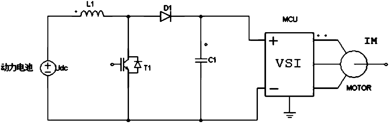
[0031] refer to figure 1 and figure 2 The electric vehicle includes a power battery, a drive circuit and a motor. The drive circuit includes a boost unit and a control unit. The control unit uses an MCU processor. The boost unit is used to receive the output voltage of the power battery and output a boosted voltage to the motor. The boost unit outputs control signals. The boost unit includes an inductor L1, a switching device T1, a diode D1, and a capacitor C1. The switching device T1 can be a MOSFET or an IGBT tube. The first end of the inductor L1 is connected to the positive pole of the power battery 11, and the second end of the inductor L1 is connected to the switching device T1. The first end of the switching device T1 is connected to the anode of the diode D1, the cathode of the diode D1 is connected to the first end of the capacitor C1, and the second end of the switching device T1 is connected to the negative electrode of the power battery 11 and the second end of t...


PUM


Abstract

The invention provides a control method and control unit of a driving circuit of an electric vehicle as well as the electric vehicle. The driving circuit comprises a boost unit and the control unit, wherein the boost unit is used for receiving the output voltage of a power battery and used for outputting booster voltage to a motor; and the control unit is used for outputting a control signal to the boost unit. The control method comprises the following steps of obtaining the running state of the electric vehicle, wherein the running state comprises a required output voltage; and judging operating state, wherein the operating state judging step comprises the following steps of judging whether the required output voltage is greater than a preset value, if the required output voltage is greater than or equal to the preset value, enabling the boost unit to start operating, enabling the boost unit to output the booster voltage to the motor, and if the required output voltage is smaller thanthe preset value, enabling the boost unit to stop operating. According to the control method and the control unit disclosed by the invention, through obtaining the running state, the system efficiency is improved, so that the problems of reduction of the torque of high-speed running of the motor, and the weak magnetism heating of a permanent magnet synchronous motor are effectively solved, and the problem that the high-speed output power of the motor is reduced caused by the reduction of the battery voltage can also be solved.

Description

technical field [0001] The invention relates to the field of new energy vehicles, in particular to a control method for an electric vehicle drive circuit, a control unit and an electric vehicle. Background technique [0002] Because electric vehicles do not burn gasoline to generate power, they are environmentally friendly and less polluting. They are widely used in places with high environmental requirements such as tourist attractions. The existing battery car is provided with a motor controller, which is used to convert the DC power outputted by the battery into a three-phase AC power and drive the motor to rotate. [0003] Electric vehicles have high requirements on the efficiency of the drive system due to the battery power supply. At present, only high-efficiency asynchronous motors or permanent magnet synchronous motors can be used to solve the problem. Due to the improvement of motor efficiency, the cost has increased significantly. Contents of the invention [0...

Claims


Application Information

Patent Timeline
IPC IPC(8): B60L15/20
CPCB60L15/2045B60L2240/427Y02T10/72
Inventor 李红雨刘宏鑫魏标
Owner ZHUHAI ENPOWER ELECTRIC
Why Eureka
Try Eureka