
Line scribing pin for machining by computer numerical control milling machine

A CNC milling machine and scribing pin technology, which is applied to manufacturing tools, workshop equipment, etc., can solve the problems of inability to draw side contours, cumbersome production, and numerous processes, so as to avoid multiple disassembly and assembly of workpieces, improve machining accuracy, simple structure

Pending Publication Date: 2018-03-02
柳州市钜嘉机械有限公司
View PDF8 Cites 0 Cited by
  • Summary
  • Abstract
  • Description
  • Claims
  • Application Information

AI Technical Summary

Problems solved by technology

The existing three-axis CNC milling machine can only process the surface of the workpiece, and can draw the hole position and outline of the front of the workpiece, but the outline of the side cannot be drawn
The previous processing method is to divide the workpiece into pieces, process the angles separately, and finally stick them together with glue. This method has many procedures and is cumbersome to produce.
If you switch to a five-axis CNC milling machine, the cost will be too high

Method used


Image

  • Line scribing pin for machining by computer numerical control milling machine
  • Line scribing pin for machining by computer numerical control milling machine

Examples


Embodiment Construction

[0019] In order to make the purpose, technical solution and advantages of the present invention clearer, the technical solution of the present invention will be described in detail below. Apparently, the described embodiments are only some of the embodiments of the present invention, but not all of them. Based on the embodiments of the present invention, all other implementations obtained by persons of ordinary skill in the art without making creative efforts fall within the protection scope of the present invention.

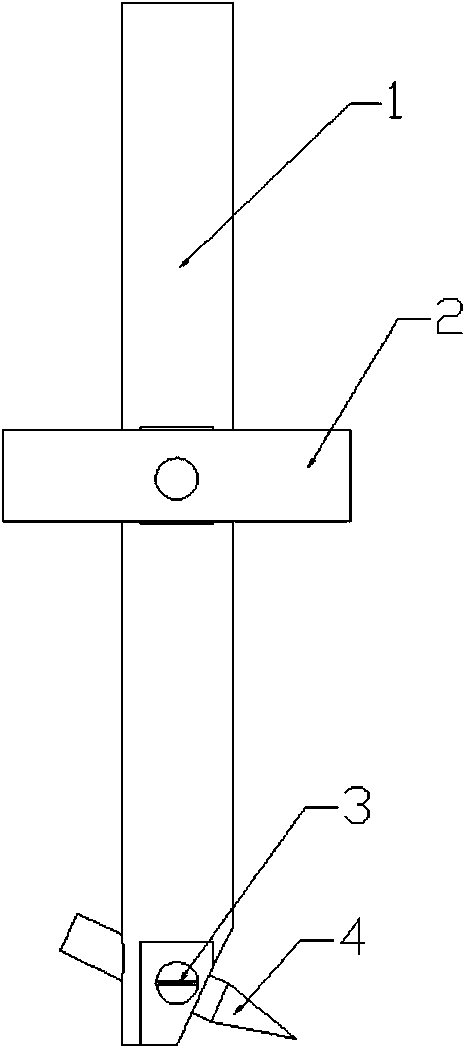
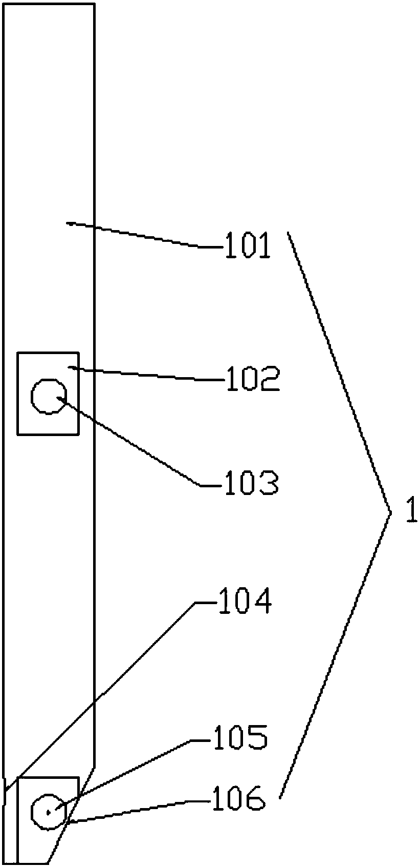
[0020] see Figure 1-Figure 2 As shown, the present invention provides a numerical control milling machine processing marking pin, including a marking pin rod 1 and a marking needle 4, the marking needle 4 is obliquely installed on one end of the marking pin rod 1 and the needle head extends out of the marking line One side of the pin rod 1 can form a certain angle with the side wall of the workpiece according to the need, and the needle head can be in contact ...


PUM


Abstract

The invention discloses a line scribing pin for machining by a computer numerical control milling machine. The line scribing pin comprises a line scribing pin rod and a scribing needle, wherein the scribing needle is obliquely mounted at one end of the line scribing pin rod; a scribing needle head extends out of one side of the line scribing pin rod; and the other end of the line scribing pin rodis fixedly mounted with a spindle of the computer numerical control milling machine. The line scribing pin has the following beneficial effects: when a structure adopting the line scribing pin is fixedly mounted with a machine tool spindle, a certain angle is formed between the scribing needle and the side wall of a workpiece, and the machine tool spindle moves according to a program, so that a workpiece contour line and hole site can be scribed on the side wall of the workpiece; the line scribing pin is simple in structure, so that the repeated dismounting and mounting of the workpiece can beavoided, that is, all the line scribing work can be completed through one-time clamping operation; and accordingly, the machining and assembling efficiency can be improved, and the workpiece machining precision can also be improved.

Description

technical field [0001] The invention relates to the field of marking pin structures, in particular to a numerically controlled milling machine for machining a marking pin. Background technique [0002] In the processing and manufacture of inspection tools for auto parts, most of the workpieces need to draw the contour line and hole position of the part on the side wall of the profile, so as to detect the material edge and hole position of the part. The existing three-axis CNC milling machine can only process the profile of the workpiece, and can draw the hole position and outline of the front of the workpiece, but the outline of the side cannot be drawn. In the past, the processing method is to divide the workpiece into pieces, process the angles separately, and finally stick them together with glue. This method has many procedures and is cumbersome to produce. If it is processed by a five-axis CNC milling machine, the cost will be too high. Contents of the invention [...

Claims


Application Information

Patent Timeline
Patent Type & Authority Applications(China)
IPC IPC(8): B25H7/04
CPCB25H7/04B25H7/045
Inventor 袁昌荣程志昌杨家信
Owner 柳州市钜嘉机械有限公司
Learn More