Electric type transformer cooling fin cleaning device

A technology for cleaning devices and transformers, applied in chemical instruments and methods, cleaning methods and utensils, and cleaning methods using liquids, etc., can solve the problems of waste of material resources, long operation time, poor flexibility, etc. Cooling effect, the effect of improving work efficiency

Pending Publication Date: 2018-03-02
国网江西省电力有限公司超高压分公司 +1
View PDF9 Cites 0 Cited by
  • Summary
  • Abstract
  • Description
  • Claims
  • Application Information

AI Technical Summary

Problems solved by technology

There is a waste of manpower and material resources during the operation process, and it is difficult to ensure that the cleaning operation is completed within the specified maintenance time limit when the operation time is limited, especially when the operation time is limited.
If the heat sink of the transformer cooling device needs to be cleaned with electricity, the safety is also relatively poor. There may be discharges caused by the unsatisfactory safe distance between the water column and the live parts, grounding and short circuits caused by water entering the cooling device control power terminal box, etc., which affect the safe operation of the power grid. event happened
[0003] In the cleaning operation and maintenance of the transformer cooling device, it is now mainly to use a large container of water as the water source and combine it with a high-pressure water pump as a cleaning device or equipment for the heat sink of the transformer cooling device. The main problems of this method are: First, there is a large demand for manpower; second, the work process is cumbersome; third, there are no safety protection measures for transformers and operators in live operation; fourth, the operation takes a long time; Restrictions will be imposed on location changes requiring mobile devices, etc.

Method used

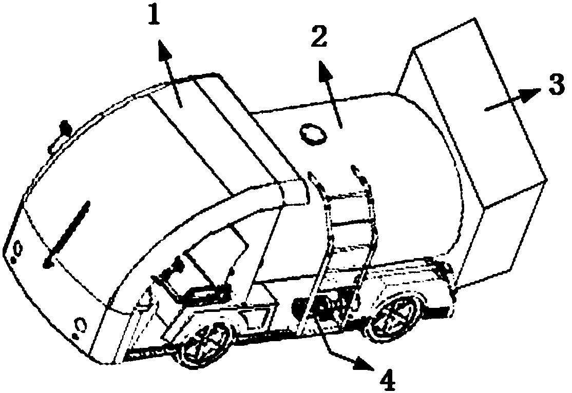
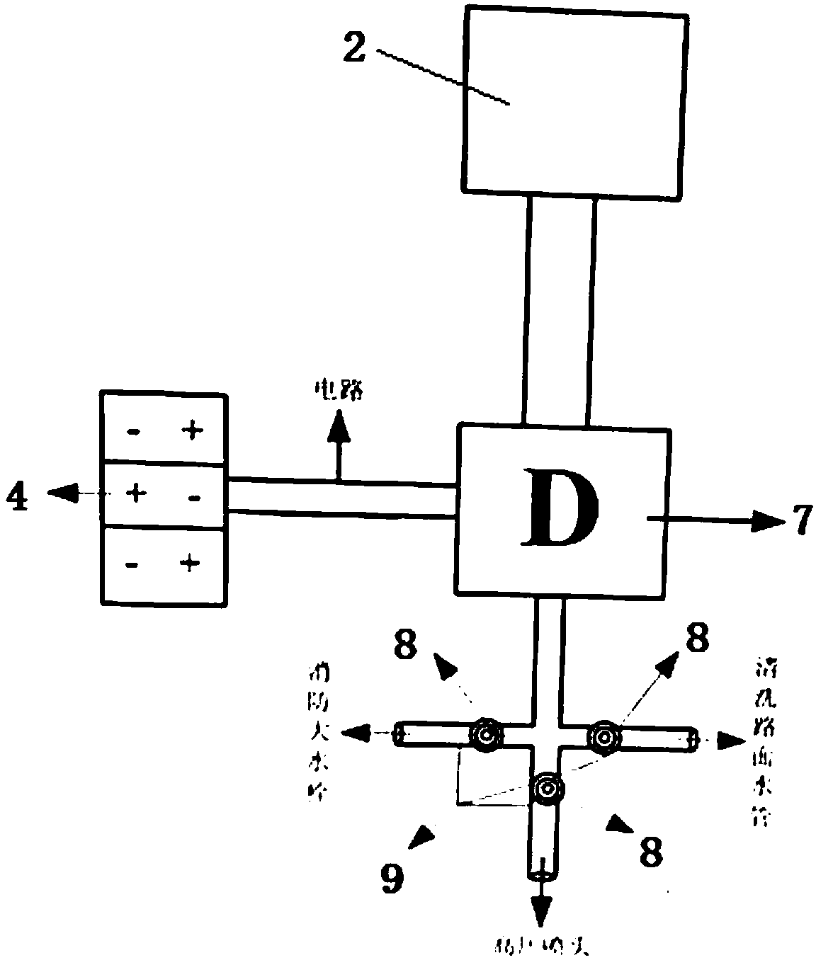

Image

  • Electric type transformer cooling fin cleaning device
  • Electric type transformer cooling fin cleaning device
  • Electric type transformer cooling fin cleaning device

Examples


Embodiment Construction

[0016] The following will clearly and completely describe the technical solutions in the embodiments of the present invention with reference to the accompanying drawings in the embodiments of the present invention. Obviously, the described embodiments are only some, not all, embodiments of the present invention. Based on the embodiments of the present invention, all other embodiments obtained by persons of ordinary skill in the art without making creative efforts belong to the protection scope of the present invention.

[0017] In the large-scale substation of 220 kV and above in the power system, the transformer is one of the important equipment of the substation, and its normal operation directly affects the safe operation of the power grid. When the transformer is running, the heat generated by itself is conducted to the heat sink by the transformer oil thermal cycle, and then the heat exchange is completed between the heat sink and the air. The heat dissipation effect of t...


PUM


Abstract

The invention discloses an electric type transformer cooling fin cleaning device. The electric type transformer cooling fin cleaning device comprises an electric car, a water tank is arranged on the electric car, a trunk is fixedly arranged on the tail of the electric car, a direct flow self-suction water pump control switch, a high-pressure water pipe and a direct flow self-suction water pump arearranged in the trunk, a storage battery set is electrically connected with the direct flow self-suction water pump through the a direct flow self-suction water pump control switch, the water tank isconnected with the direct flow self-suction water pump through a water path, and the device can more conveniently, safely and reliably perform electrified water flushing mobile work. Work efficiencycan be improved, manual cost is saved, the unsafe factor possibly appearing in the electrified water flushing work can be solved, the cooling effect of a transformer can be improved, the service lifeof the transformer can be prolonged, and the aims of protecting persons, equipment and power nets can be achieved.

Description

technical field [0001] The invention relates to the field of electrical equipment in a power system, in particular to an electric transformer cooling fin cleaning device. Background technique [0002] At present, its structure of known transformer cooler device cooling fin cleaning device is mainly composed of spray gun, high-pressure water pipe, AC high-pressure pump, water holding equipment (when there is no water source in the transformer field area), power line reel, and water pipe. There is a waste of manpower and material resources during the operation process, and it is difficult to ensure that the cleaning operation is completed within the specified maintenance time limit when the operation time is limited, especially when the operation time is limited. If the heat sink of the transformer cooling device needs to be cleaned with electricity, the safety is also relatively poor. There may be discharges caused by the unsatisfactory safe distance between the water column ...

Claims


Application Information

Patent Timeline
Patent Type & Authority Applications(China)
IPC IPC(8): B08B3/02B08B13/00
CPCB08B3/02B08B13/00
Inventor 时小红田国稳占添乐汪旭峰周丽群邹明吴康欶传通胡军平黄斌
Owner 国网江西省电力有限公司超高压分公司
Why Eureka
Try Eureka