Intelligent control switch and control method thereof

A technology of intelligent control and switch, applied in the direction of program control, computer control, comprehensive factory control, etc., can solve the problems of user inconvenience, inability to obtain power consumption parameter information of electrical equipment, affecting the development of smart home, etc., to reduce energy consumption. Effect

Inactive Publication Date: 2018-02-27
湖州舒佳电器工程有限公司
View PDF0 Cites 0 Cited by
  • Summary
  • Abstract
  • Description
  • Claims
  • Application Information

AI Technical Summary

Problems solved by technology

The defect of this type of switch is: if the intelligent control switch fails (such as a relay failure), then the switch will no longer work, and home appliances such as lighting will "can't be turned on or off if you want to". Cause great inconvenience and distress to users, so as to affect the development of smart home industry
However, the existing switches are mainly used to control the power supply of electrical appliances / electrical equipment, and the relevant power consumption parameter information of the electrical equipment cannot be obtained.
Although some patent documents mention that the switch provided in the smart home system has the function of detecting and displaying the voltage, current, and power consumption of the electrical equipment, the user still cannot know the function of the electrical equipment through the switch connected to the electrical equipment. Information such as the power consumption consumed by electrical equipment, therefore, the existing switches cannot meet the needs of users

Method used


Image

  • Intelligent control switch and control method thereof
  • Intelligent control switch and control method thereof

Examples


Embodiment 1

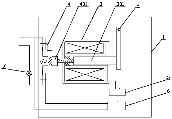
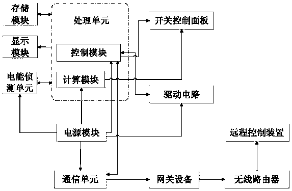
[0028] Embodiment 1: as figure 1 , 2 As shown, the intelligent control switch includes a switch box body 1, a switch control panel with several buttons 2, and a processing unit installed in the switch box body 1, a storage unit, an electric energy detection unit, a communication unit, a power supply unit, and a The circuit board of the drive circuit 5, the switch control panel is provided with a display module, the storage unit, the electric energy detection unit and the display module are all electrically connected to the processor, and the processing unit includes a control module 6 and a computing module, so The drive circuit 5 is electrically connected to the control module 6, the control module 6 and the calculation module are electrically connected to the switch control panel, the control module 6, the calculation module, the electric energy detection unit, the drive circuit 5 and the communication unit are all connected to the power supply The unit is electrically conn...

Embodiment 2

[0036] Embodiment 2: as figure 1 , 2 As shown, the local control method of the intelligent control switch includes the following steps:

[0037] S1: Connect the power cord to the fire wire of the load 7 through the self-locking key switch 4, and the self-locking key switch 4 and the electromagnet are all fixed in the switch box body 1;

[0038] S2: The key head 401 of the self-locking key switch 4 touches one end of the electromagnet push rod, and the other end of the push rod is fixedly connected to one end of the movable iron core; the other end of the movable iron core is connected to the key of the push-button switch touch;

[0039] S3: Press the key of the key switch, the movable iron core of the electromagnet presses the key head 401 of the self-locking key switch 4 through the push rod, and changes the current on-off state of the load 7;

[0040] S4: After the key action is completed, the key head 401 of the self-locking key switch 4 is reset under the action of the ...

Embodiment 3

[0043] Embodiment 3: as figure 1 , 2 As shown, the remote control method of the intelligent control switch includes the following steps:

[0044] S1: Access the gateway device through a wireless router, and press the icon of the corresponding load 7 on the remote control device;

[0045] S2: the gateway device sends an instruction to the control module 6 of the intelligent control switch through the wireless two-way communication unit;

[0046] S3: The control module 6 drives the electromagnet to act through the instantaneous current of the drive circuit 5, the movable iron core is attracted to the fixed iron core under the action of the electromagnetic field, and the push rod drives the self-locking key switch 4 to act, changing the current of the load 7 on-off state;

[0047] S4: After the instantaneous action of the electromagnet is completed, the electromagnetic field disappears, and the key head 401 of the self-locking key switch 4 is reset under the action of the inte...


PUM


Abstract

The invention relates to the technical field of electronic control switches, in particular to an intelligent control switch and a control method thereof. The intelligent control switch comprises a switch box body, a switch control panel with a plurality of keys, a processing unit, a storage unit, an electric energy detecting unit, a communication unit, a power unit and a circuit board provided with a driving circuit, and the processing unit, the storage unit, the electric energy detecting unit, the communication unit and the power unit are installed in the switch box body. A display module isarranged on the switch control panel, the storage unit, the electric energy detecting unit and the display module are all electrically connected with a processor, the processing unit comprises a control module and a computing module, and the driving circuit is electrically connected with the control module. The control module and the computing module are both electrically connected with the switchcontrol panel, and the control module, the computing module, the electric energy detecting unit, the driving circuit and the communication unit are all electrically connected with the power unit. According to the intelligent control switch and the control method thereof, a user can directly check the real-time electricity information and electricity consumption of electric equipment connected with the intelligent control switch visually and conveniently through the display unit, and therefore the needs of the user are met.

Description

technical field [0001] The technical field of the electric control switch of the present invention particularly relates to an intelligent control switch and a control method thereof. Background technique [0002] With the development of science and technology and the improvement of living standards, smart home has been paid more and more attention by people. While smart home provides comfortable life, it also creates conditions for energy saving and utilization. In today's emphasis on low-carbon, energy-saving, and environmental protection, the smart home industry will be well developed. Smart control switches are key products in smart homes; there are various smart control switches on the market at present, and these smart control switches are composed of communication units, control modules, power modules, drive circuits and actuators. The actuator is usually a relay, and the current of the household appliance is turned on and off through the pull-in and disconnection of...

Claims


Application Information

Patent Timeline
IPC IPC(8): G05B15/02G05B19/418H01H3/28
CPCY02P90/02G05B15/02G05B19/418G05B2219/2642H01H3/28
Inventor 李善鹏
Owner 湖州舒佳电器工程有限公司
Why Eureka
Try Eureka