
Damping device of impact type machine foundation

A technology of machine foundation and vibration damping device, applied in the direction of non-rotational vibration suppression, etc., can solve the problems of ground or object shaking in the workshop, complex structure of vibration damping device, influence of surrounding buildings, etc., to optimize the space size and mechanical performance, Effective frequency shifting and energy consumption, ensuring the effect of running stability

Active Publication Date: 2018-02-27
WUHAN UNIV OF TECH
View PDF9 Cites 0 Cited by
  • Summary
  • Abstract
  • Description
  • Claims
  • Application Information

AI Technical Summary

Problems solved by technology

[0002] With the development of industrial modernization, the degree of mechanization of various production activities is becoming more and more extensive. A large number of power machines are put into processing and production, which makes the production efficiency higher and higher. However, the normal operation stage of power machines will cause obvious damage to the ground or objects in the factory building. The shaking affects the working environment of the staff and the normal use of precision instruments and equipment, and also affects the surrounding buildings
In particular, some large-scale impact machines have caused serious environmental vibration problems during normal operation. With the development of social economy and the improvement of people's quality of life, the impact of vibration on the environment must be controlled, but there are existing vibration reduction devices. Due to the complex structure, high cost, and limited implementation conditions, it is urgent to propose a practical and effective vibration reduction measure to reduce the environmental vibration caused by the operation of impact machines.

Method used


Image

  • Damping device of impact type machine foundation
  • Damping device of impact type machine foundation
  • Damping device of impact type machine foundation

Examples


Embodiment Construction

[0016] In order to make the object, technical solution and advantages of the present invention clearer, the present invention will be further described in detail below in conjunction with the accompanying drawings and embodiments. It should be understood that the specific embodiments described here are only used to explain the present invention, not to limit the present invention.

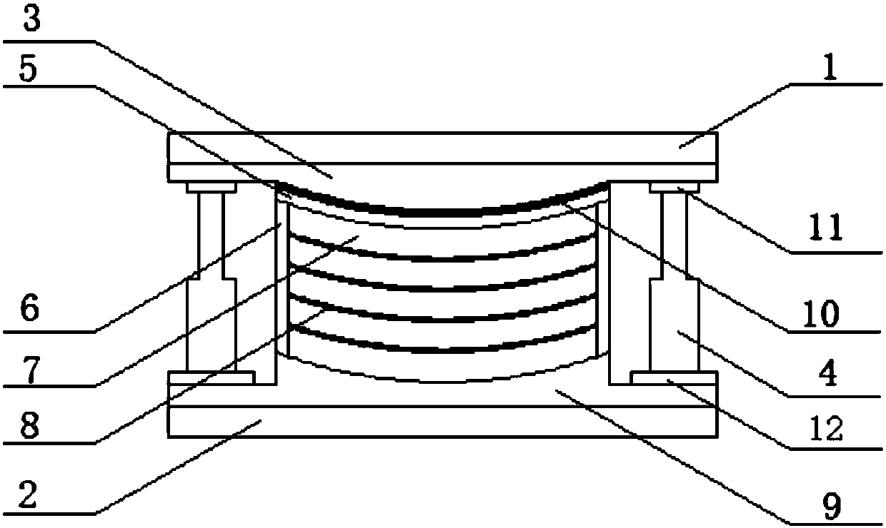
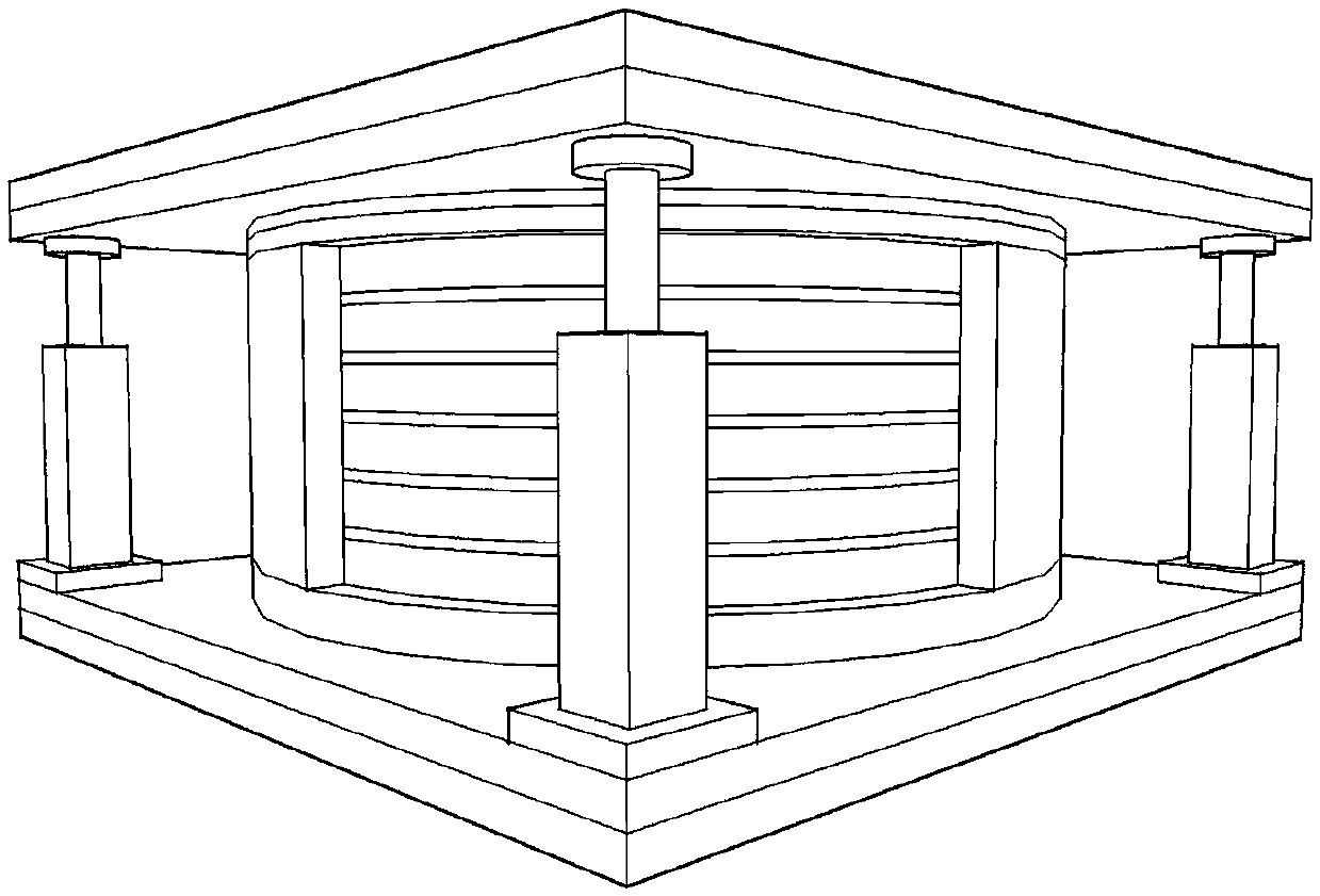
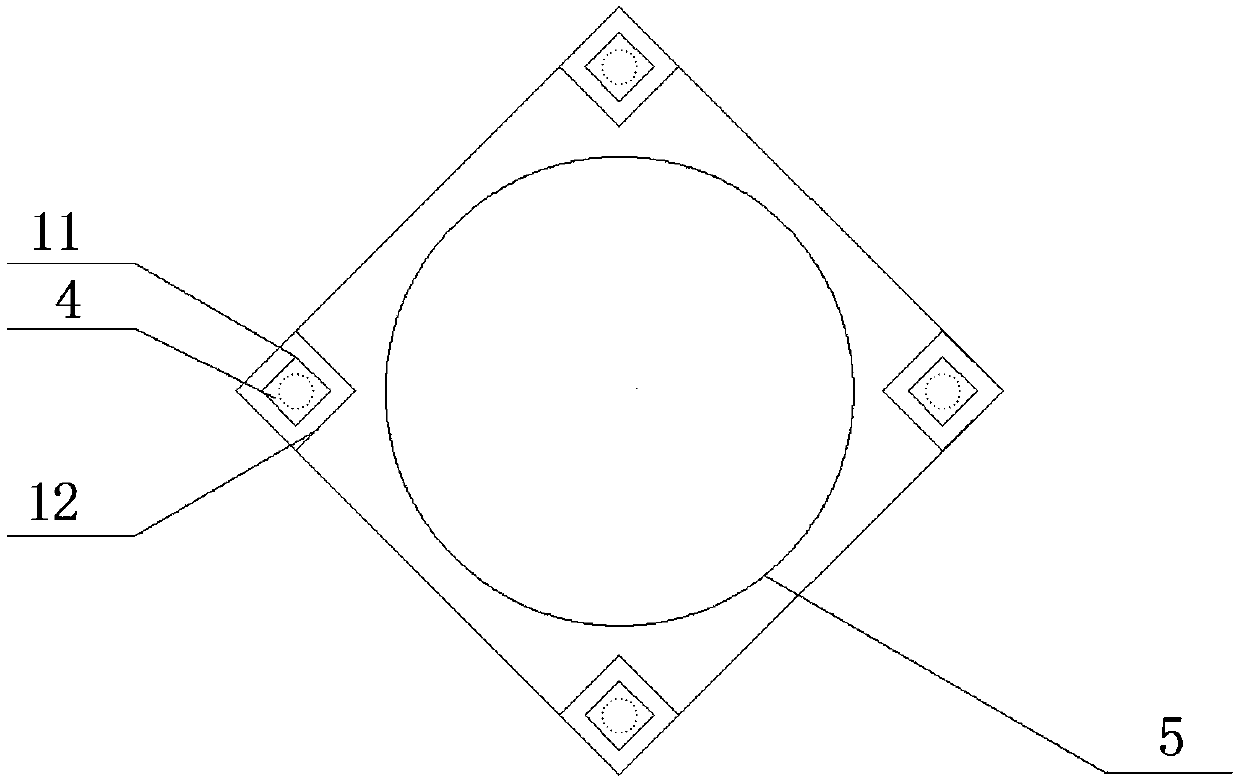
[0017] In an embodiment of the present invention, a vibration damping device for an impact machine foundation is provided, including a frame, a spherical rubber block, a damper, a spherical crown liner, and a spherical PTFE plate. The frame is in the shape of a cube, and the frame includes a base, The upper connecting plate, the lower connecting plate, the base and the lower connecting plate are fixed, the spherical rubber block is set in the middle of the frame, and the 4 dampers are respectively set at the four corners of the base, vertically set up with the upper connecting plate and the lower co...


PUM


Abstract

The invention discloses a damping device of an impact type machine foundation. A spherical rubber block and a damper are adopted for combined damping. The spherical rubber block is formed by means ofthe method that a plurality of layers of spherical rubber plates and spherical steel plates are embedded, stuck and vulcanized, and the vertical rigidity of the spherical rubber block can ensure bearing force on an impact type machine. Meanwhile, the inherent frequency of the impact type machine foundation can be adjusted to get away from the impact load frequency, and the inlaid spherical steel plates of the spherical rubber block can effectively restrain lateral expansion of rubber and provide radial restraining counterforce to limit horizontal displacement of the impact type machine so as to ensure the operation stability of the impact type machine. Through the layout scheme of the damper, the spatial size and mechanical performance of the damping device can be optimized, and the impactenergy of the impact type machine is rapidly consumed to enable the impact type machine to rapidly recover to a balancing position. Therefore, the damping device can provide effective frequency shiftand energy consumption effects, so that the damping function of the impact type machine is achieved, the operation stability of the impact type machine is ensured, and the vibration influence of operation of the impact type machine on surroundings can also be reduced.

Description

technical field [0001] The invention belongs to the technical field of vibration control, in particular to a vibration damping device for an impact machine foundation. Background technique [0002] With the development of industrial modernization, the degree of mechanization of various production activities is becoming more and more extensive. A large number of power machines are put into processing and production, which makes the production efficiency higher and higher. However, the normal operation stage of power machines will cause obvious damage to the ground or objects in the factory building. The shaking affects the working environment of the staff and the normal use of precision instruments and equipment, and also affects the surrounding buildings. In particular, some large-scale impact machines have caused serious environmental vibration problems during normal operation. With the development of social economy and the improvement of people's quality of life, the impac...

Claims


Application Information

Patent Timeline
Patent Type & Authority Applications(China)
IPC IPC(8): F16F15/08F16F15/02
CPCF16F15/02F16F15/08
Inventor 孙亮明刘晓艳周连江刘汉赋赵寒冰
Owner WUHAN UNIV OF TECH
Learn More