Design method of movable wind barriers synchronized with vehicles on long-span bridges

A wind barrier and vehicle technology, applied in the field of movable wind barriers, can solve the problems of low cost performance, large lateral force load of bridges, and low reliability, and achieve the effects of small wind resistance area, high safety factor, and high reliability

Active Publication Date: 2019-08-06
TONGJI UNIV
View PDF7 Cites 0 Cited by
  • Summary
  • Abstract
  • Description
  • Claims
  • Application Information

AI Technical Summary

Problems solved by technology

Traditional bridge wind barriers are divided into two types: continuous wind barriers and partial wind barriers. Although continuous wind barriers are more effective, they are less cost-effective and tend to be conservative. Although local wind barriers can ensure driving safety in most cases, they are not It is difficult to guarantee its function when there is an occasional crosswind, and the reliability is low
The main problem of traditional wind barriers is that the installation, construction and post-maintenance are more complicated. At the same time, the most serious problem is that the installation of wind barriers will add a large lateral force load to bridges (especially suspension bridges), which makes the failure probability of bridges Greatly improved, facing greater security and economic risks
[0005] In previous studies, few movable local wind barrier safety facilities were involved

Method used


Image

  • Design method of movable wind barriers synchronized with vehicles on long-span bridges
  • Design method of movable wind barriers synchronized with vehicles on long-span bridges
  • Design method of movable wind barriers synchronized with vehicles on long-span bridges

Examples


Embodiment 1

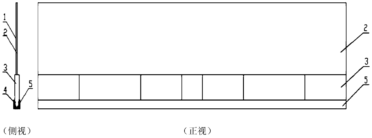
[0035] The whole movable wind barrier system is composed of three parts: wind barrier main body, slide rail and power device.

[0036] 1. The main body of the wind barrier

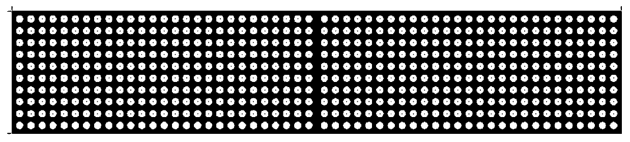
[0037] In order to weaken the impact of crosswind on the driving safety of long-span bridges, it is necessary to configure the porosity of the wind barrier when designing the porous windshield or anti-parabolic fence. The size of the wind barrier porosity directly determines the size of the wind barrier effect. According to the simulation experiment analysis, the figure 1 The porosity of the middle wind barrier is controlled at 30%-50%. At this time, the wind barrier can not only effectively reduce the wind speed on the bridge deck, but also reduce the sudden change of wind speed outside the bridge tower and the decline of stability.

[0038] Considering the body size of large transport vehicles, the height of the entire mobile wind barrier should be about 3.0m and the length should be about 15m, which ca...


PUM


Abstract

A novel movable wind barrier design method applied on long-span bridges synchronously with vehicles, including wind barrier main body, slide rail and power device. The power device includes a moving wind barrier following system and a power system. The follow-up system utilizes video recognition technology and is implemented by installing a camera on the supporting structure of the mobile wind barrier; the position of the mobile wind barrier and the camera are located on both sides of the bridge, and the recognition and positioning of the vehicle is realized by capturing the wheels of the vehicle. The power system uses an electric motor as an energy source, and realizes the movement of the entire mobile wind barrier by driving the rollers of the power device; the wind barrier part of the mobile wind barrier is attached with a solar panel, which supplies power to the electric motor, and when the mobile wind barrier is not working The electric energy can be stored at any time; the power system can control its own power output by following the relative position information of the vehicle fed back by the system, and adjust the movement speed to realize synchronous movement with the protected vehicle.

Description

technical field [0001] The invention belongs to the technical field of traffic safety design, and in particular relates to a movable wind barrier applied to a long-span bridge that can move synchronously with vehicles traveling on the bridge. Background technique [0002] Due to my country's vast territory and changeable climate, traffic safety is affected by various weather factors. Among them, there are generally strong cross winds in sections such as mountain passes, passes, high roadbed bends, and long-span bridges. The wind in the natural environment is an important external factor that affects the stability and safety of vehicles such as vehicles. For vehicles, the main hazard is the effect of crosswinds. In coastal cities where typhoons are frequent, there are reports of vehicles overturning caused by crosswinds every year, and this phenomenon is particularly serious on bridges. Crosswind has a great influence on the stability of the vehicle, because when the wind ...

Claims


Application Information

Patent Timeline
Patent Type & Authority Patents(China)
IPC IPC(8): E01F8/00G06K9/00
CPCE01F8/00G06V20/584G06V2201/08
Inventor 陈培焱陈丰潘晓东
Owner TONGJI UNIV
Why Eureka
Try Eureka