
Transformation calibration method and system for mechanical arm coordinate system

A coordinate system and robotic arm technology, applied in the field of robot control and application, can solve the problems that the reliability of the coordinate system cannot be guaranteed, and the position error of the TCP point of the end tool relative to the base coordinate system is not considered, so as to reduce the time-consuming calibration and facilitate on-site Operation, the effect of improving the calibration accuracy

Active Publication Date: 2018-02-27
INST OF MICROELECTRONICS CHINESE ACAD OF SCI
View PDF5 Cites 39 Cited by
  • Summary
  • Abstract
  • Description
  • Claims
  • Application Information

AI Technical Summary

Problems solved by technology

The single-axis rotation motion method uses three single-axis periodic rotations, combined with the space geometry vector and the coordinate system transformation equation to solve the problem. The translation vector of the end tool coordinate system depends on the measurement accuracy of the single point of the spatial intersection point, and does not consider the relative position of the current end tool TCP point. The position error of the base coordinate system, so the reliability of the calibration accuracy of the coordinate system cannot be guaranteed

Method used


Image

  • Transformation calibration method and system for mechanical arm coordinate system
  • Transformation calibration method and system for mechanical arm coordinate system
  • Transformation calibration method and system for mechanical arm coordinate system

Examples


Embodiment Construction

[0024] In order to make the purpose, technical solutions and advantages of the present invention clearer, the technical solutions in the present invention will be clearly and completely described below in conjunction with the accompanying drawings in the embodiments of the present invention. Obviously, the described embodiments are the embodiment of the present invention. Some, but not all, embodiments. Based on the embodiments of the present invention, all other embodiments obtained by persons of ordinary skill in the art without making creative efforts belong to the protection scope of the present invention.

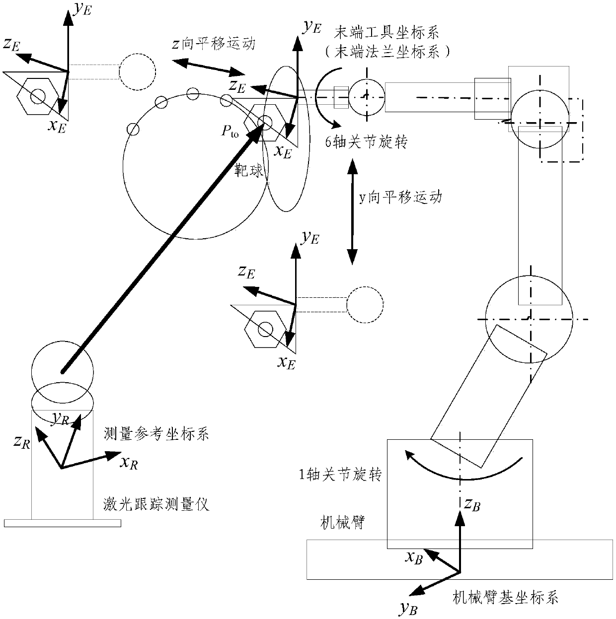
[0025] As an aspect of the embodiment of the present invention, this embodiment provides a method for transforming and calibrating the coordinate system of the manipulator, refer to figure 1 , is a schematic layout diagram of a manipulator space coordinate system transformation and calibration according to an embodiment of the present invention. When arranging the tar...


PUM


Abstract

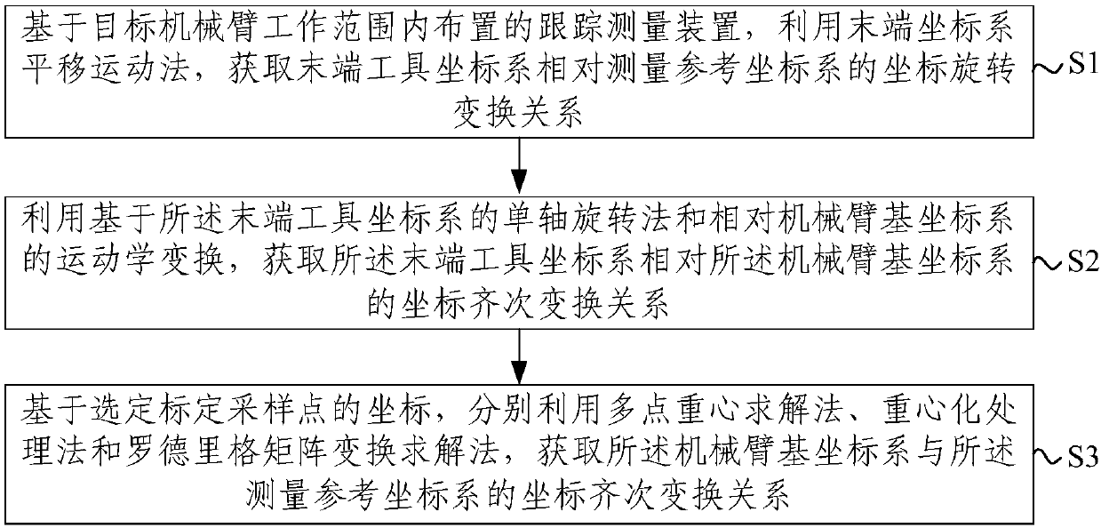
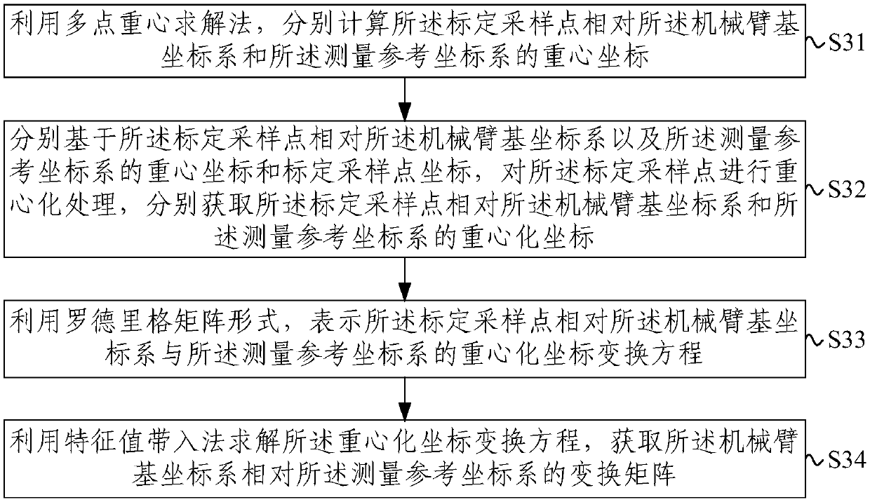
The invention provides a transformation calibration method and system for a mechanical arm coordinate system. The transformation calibration method comprises the steps that S1, based on a tracking measurement device arranged in the working range of a target mechanical arm, the coordinate rotation transformation relation of a tail end tool coordinate system relative to a measurement reference coordinate system is obtained through a tail end coordinate system translational movement method; S2, the coordinate homogeneous transformation relation of the tail end tool coordinate system relative to amechanical arm base coordinate system is obtained through a single-axial rotation method based on the tail end tool coordinate system and kinematic transformation relative to the mechanical arm basecoordinate system; and S3, based on coordinates of selected calibration sampling points, the coordinate homogeneous transformation relation of the mechanical arm base coordinate system and the measurement reference coordinate system is obtained through a multipoint gravity center solution method, a gravity center processing method and a Roderick matrix transformation solution method. The calibration procedure is simple, the calibration algorithm is free of the iterative process, the consumed time of coordinate calibration can be effectively reduced, and the calibration precision of the coordinate systems is improved.

Description

technical field [0001] The present invention relates to the technical field of robot control and application, and more specifically, to a method and system for converting and calibrating a mechanical arm coordinate system. Background technique [0002] Industrial manipulators usually use the tool coordinate system to represent the position of the Tool Center Point (TCP) of the end tool and the attitude of the end tool. The pose control of the tool at the end of the manipulator depends on the kinematic transformation relationship of the robot relative to the base coordinate system. However, in the external measurement process, the measured value of the end tool pose is relative to the measurement reference coordinate system, and the conversion calibration between the measurement reference coordinate system and the relevant coordinate system of the manipulator must be carried out to obtain the end tool coordinate system of the manipulator and the base coordinate system of the ...

Claims


Application Information

Patent Timeline
Patent Type & Authority Applications(China)
IPC IPC(8): B25J9/16G06T7/80
CPCB25J9/1602B25J9/161G06T7/80
Inventor 杨聚庆董登峰周维虎劳达宝纪荣祎张滋黎袁江石俊凯王岩庆范百兴王国名程智朱志忠
Owner INST OF MICROELECTRONICS CHINESE ACAD OF SCI
Learn More