
Method for detecting images with brightness abnormality and LED display screen uniformity correction method

A technology of LED display and uniformity correction, which is applied in the direction of static indicators, instruments, etc., can solve the problems of camera or screen being blocked, time-consuming increase, affecting visual viewing effect, etc., so as to ensure safety and effectiveness and save correction Time, avoiding the effect of correcting the blurred screen phenomenon

Active Publication Date: 2015-09-09
XIAN NOVASTAR TECH
View PDF7 Cites 28 Cited by
  • Summary
  • Abstract
  • Description
  • Claims
  • Application Information

AI Technical Summary

Problems solved by technology

[0004] The most important thing in the whole calibration process is to collect the original brightness and chromaticity value of the LED display screen. At present, the LED display screen tends to be small-pitched and large-area, and the number of LED light points collected by the camera at a time is limited, so that the time spent on calibration and collection gradually increases. However, in the long acquisition process, it is entirely possible that the camera or the screen is blocked suddenly, the ambient light changes, and the screen is abnormally displayed. If the image captured at this time is used for calibration calculations, it will only degrade the screen and seriously affect the vision. viewing effect

Method used


Image

  • Method for detecting images with brightness abnormality and LED display screen uniformity correction method
  • Method for detecting images with brightness abnormality and LED display screen uniformity correction method
  • Method for detecting images with brightness abnormality and LED display screen uniformity correction method

Examples


Embodiment Construction

[0020] In order to make the above objects, features and advantages of the present invention more comprehensible, specific implementations of the present invention will be described in detail below in conjunction with the accompanying drawings.

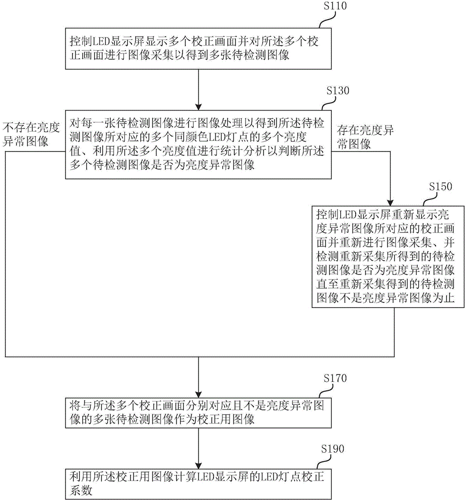
[0021] See figure 1 , which is a flow chart of a method for correcting uniformity of an LED display screen provided by an embodiment of the present invention. Such as figure 1 As shown, the method for correcting the uniformity of the LED display screen in this embodiment includes steps S110, S130, S150, S170 and S190, and the specific contents are as follows:

[0022]Step S110: controlling the LED display to display a plurality of calibration images and performing image acquisition on the plurality of calibration images to obtain a plurality of images to be detected. Wherein, the LED display screen can be a RGB three-primary color full-color LED display screen or a single / two-color LED display screen. This embodiment uses an RGB thre...


PUM


Abstract

The invention relates to a method for detecting images with brightness abnormality and an LED display screen uniformity correction method adopting the method for detecting images with brightness abnormality. After collecting target pictures (such as correction pictures) to obtain images to be detected, the method for detecting images with brightness abnormality uses a statistical method to analyze a brightness value of each LED lamp point that the images to be detected correspond to, for example, a statistical value representing an average level of brightness distribution and a statistical value representing the dispersion degree of brightness distribution are calculated, and then in combination with a set threshold range, whether each image to be detected is an image with brightness abnormality is judged. When an image with brightness abnormality is detected to exist, image acquisition is performed again individually to replace the image with brightness abnormality, thereby overcoming the problem of a blurred screen in correction which is caused by an ambient light change, a fact that an image acquisition device (such as a camera) or a screen body is shielded, a screen display abnormality and the like which may occur in a conventional correction collection process.

Description

technical field [0001] The invention relates to the technical field of LED display correction, in particular to a method for detecting an image with abnormal brightness and a method for correcting the uniformity of an LED display screen. Background technique [0002] At present, due to the limitation of the production process level in the LED display industry, there is a common phenomenon that the brightness difference of the same order and the same production batch of LED lights may reach 40%-50%. The brightness uniformity of the display screen assembled by such LED lights is generally poor. , In addition, when the LED display is used for many years, the brightness may attenuate, and the inconsistent attenuation degree of the LED light will also lead to a decrease in the uniformity of the LED display. These differences in brightness uniformity are very significant in the eyes of the human eye, so LED displays basically need to be corrected to improve the brightness uniformi...

Claims


Application Information

Patent Timeline
Patent Type & Authority Applications(China)
IPC IPC(8): G09G3/00G09G3/32
Inventor 杨城赵星梅
Owner XIAN NOVASTAR TECH
Learn More