
Current calibration coefficient measurement device, measurement method, current detection device and detection method

A current detection device and a current calibration technology, which are applied in the direction of measuring devices, digital measurement technology for measurement, measurement of electrical variables, etc., can solve the problems of current measurement battery pack measurement error, error, low measurement accuracy, etc., to reduce errors , the effect of improving the accuracy

Active Publication Date: 2018-02-23
컨템포러리엠퍼렉스테크놀로지씨오리미티드
View PDF5 Cites 42 Cited by
  • Summary
  • Abstract
  • Description
  • Claims
  • Application Information

AI Technical Summary

Problems solved by technology

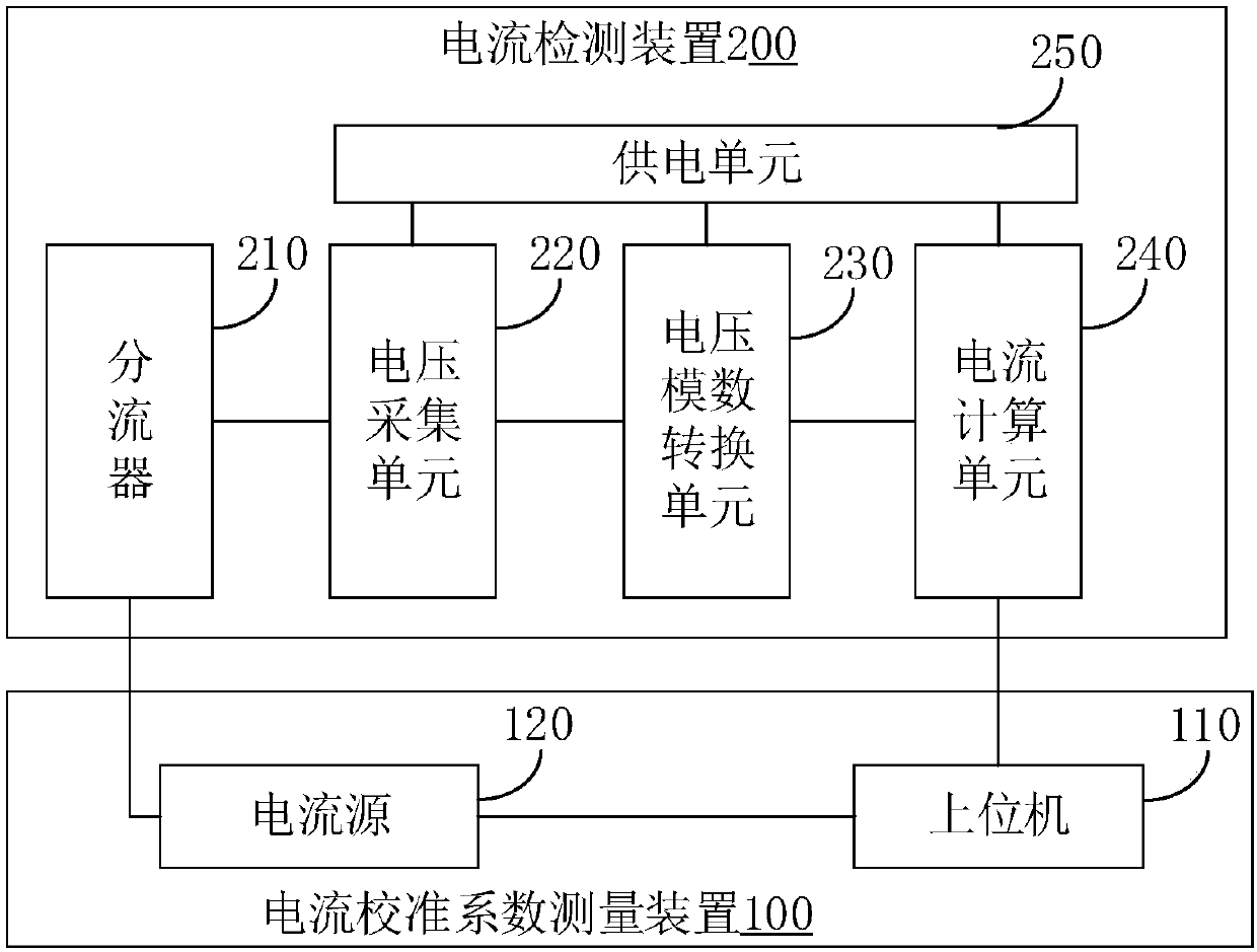
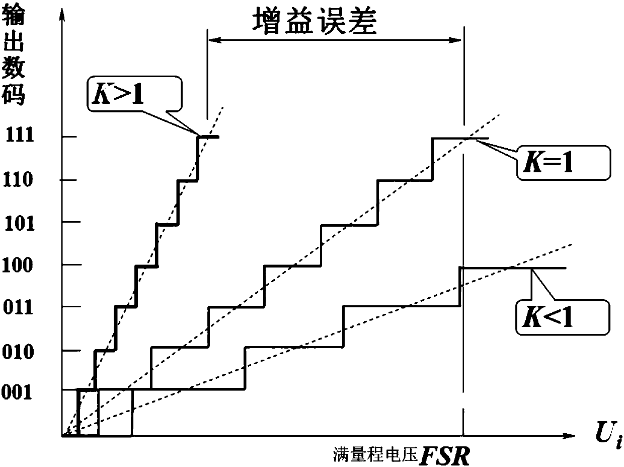
[0004] Current measurement based on the shunt is simple to implement, but in the current detection device based on the shunt, an analog-to-digital conversion circuit is required to perform analog-to-digital conversion on the voltage analog signal collected on the shunt, and the conversion process will cause the There is an error between the final voltage value and the actual sampling value, which leads to an error in the measurement result of the current value in the current measurement battery pack, and the measurement accuracy is low. At present, there is no good current measurement device based on the shunt. How to measure and calibrate

Method used


Image

  • Current calibration coefficient measurement device, measurement method, current detection device and detection method
  • Current calibration coefficient measurement device, measurement method, current detection device and detection method
  • Current calibration coefficient measurement device, measurement method, current detection device and detection method

Examples


Embodiment Construction

[0041] Features and exemplary embodiments of various aspects of the invention will be described in detail below. In the following detailed description, numerous specific details are set forth in order to provide a thorough understanding of the present invention. It will be apparent, however, to one skilled in the art that the present invention may be practiced without some of these specific details. The following description of the embodiments is only to provide a better understanding of the present invention by showing examples of the present invention. The present invention is by no means limited to any specific configurations and algorithms presented below, but covers any modification, substitution and improvement of elements, components and algorithms without departing from the spirit of the invention. In the drawings and the following description, well-known structures and techniques have not been shown in order to avoid unnecessarily obscuring the present invention.

...


PUM


Abstract

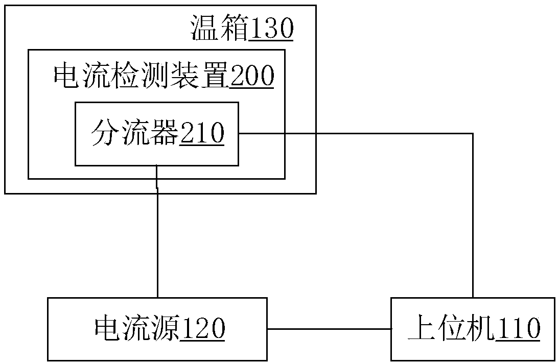
The invention discloses a current calibration coefficient measurement device, a measurement method, a current detection device and a detection method. The measurement device comprises an upper computer and a current source, wherein the current source is serially connected with a shunt of a to-be-calibrated current detection device. The current detection device also comprises a voltage acquisitionunit for acquiring voltage analog signals at two ends of the shunt, a voltage analog-digital conversion unit for carrying out analog-digital conversion on the voltage analog signals to obtain a voltage value and a current calculation unit for calculating a detection current value according to the voltage value and the nominal resistance of the shunt. The upper computer is used for controlling thecurrent source to output current at a specified current value, and according to the specified current value and the detection current value calculated by the current calculation unit, a current calibration coefficient is calculated and obtained. According to the measurement device disclosed in the embodiment of the invention, a brand new current detection device current calibration coefficient measurement scheme is provided, a current calibration basis is provided for current detection by the current detection device, and the current detection precision is improved.

Description

technical field [0001] The invention relates to the technical field of battery pack management, in particular to a current calibration coefficient measurement device and method, and a current detection device and method. Background technique [0002] The replacement of fuel vehicles by electric vehicles has become the development trend of the automobile industry. The mileage, service life and safety of battery packs are all very important for the use of electric vehicles. Therefore, it is necessary to configure a current detection device in the electric vehicle to detect the charging and discharging current value of the battery pack, so as to calculate the state of charge (SOC) of the battery pack, that is, the current available capacity, according to the measured current value. [0003] According to different current measurement principles, the existing power vehicle current detection devices mainly adopt three principles: Hall effect, fluxgate and shunt. Current sensors b...

Claims


Application Information

Patent Timeline
IPC IPC(8): G01R35/00G01R19/25
CPCG01R19/25G01R35/005G01R1/203
Inventor 侯贻真但志敏张伟许佳
Owner 컨템포러리엠퍼렉스테크놀로지씨오리미티드
Learn More