Inclined fin type parallel flow heat exchanger and production process thereof

A parallel flow heat exchanger and manufacturing process technology, applied in the direction of heat exchanger types, indirect heat exchangers, heat exchange equipment, etc., can solve the limitations of parallel flow heat exchanger quality, service life, process stability, and rationality Inadequate, affecting heat transfer efficiency and other issues, to achieve stable and reliable production process, not easy to gather and freeze, and improve product quality

Pending Publication Date: 2018-02-23
DONGGUAN FENGRUIDE TEMPERATURE CONTROL TECH CO LTD
View PDF0 Cites 1 Cited by
  • Summary
  • Abstract
  • Description
  • Claims
  • Application Information

AI Technical Summary

Problems solved by technology

In the prior art, the fins are vertically designed, and the condensed water on the surface of the fins is not drained smoothly, and it is easy to freeze, resulting in an increase in the thermal resistance of the fins, which affects the heat transfer efficiency
In addition, the parallel flow heat exchangers in the prior art have shortcomings such as process stability and poor rationality, which often lead to weak connections between parts in the parallel flow heat exchanger, large gaps, and stable Poor performance and other problems limit the quality and service life of parallel flow heat exchangers and their applied products

Method used


Image

  • Inclined fin type parallel flow heat exchanger and production process thereof
  • Inclined fin type parallel flow heat exchanger and production process thereof
  • Inclined fin type parallel flow heat exchanger and production process thereof

Examples


Embodiment Construction

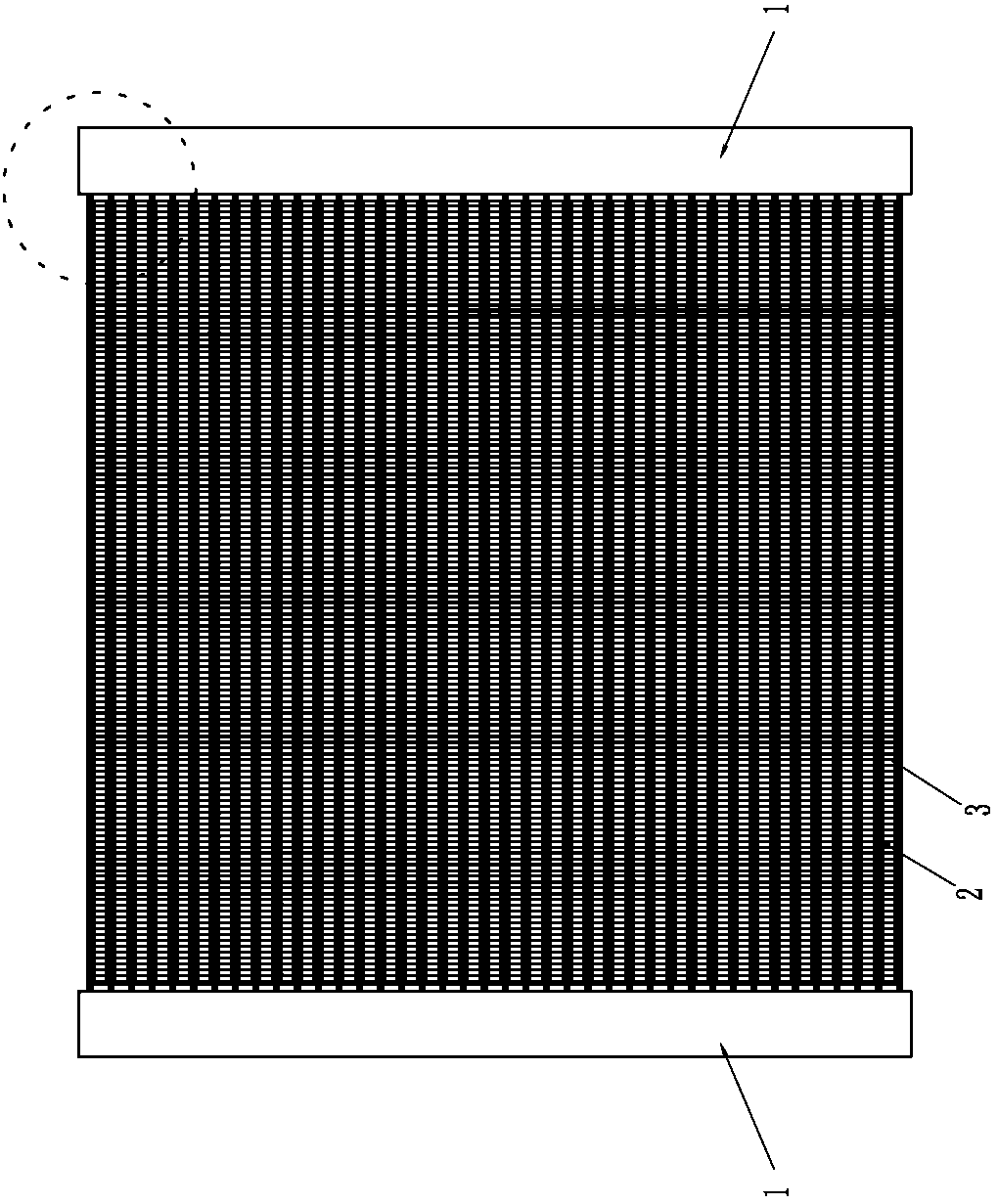
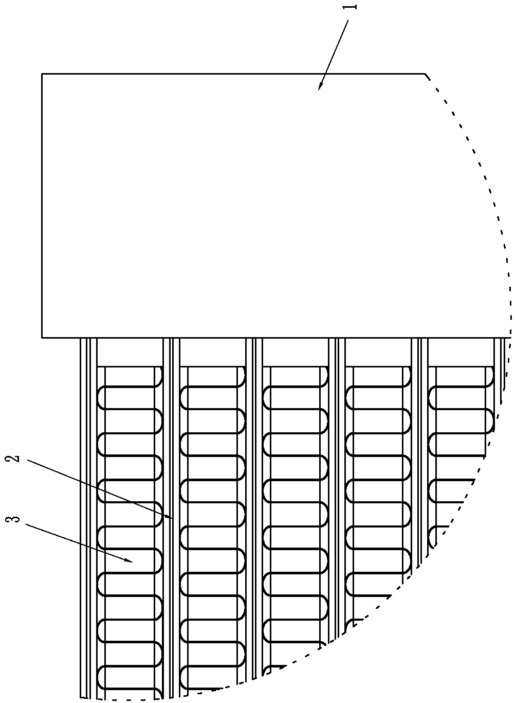
[0046] Please refer to Figure 1 to Figure 10 As shown, it shows the specific structure of the embodiment of the present invention; the inclined-fin parallel flow heat exchanger can be widely used in the fields of air conditioners, refrigerators, etc., and its structural design is simple, ingenious and reasonable, which greatly improves the heat transfer Performance, has great promotion and application value. The descriptions of directions such as "up, down, left, right, front, and back" in this article are described by taking the illustrations in the drawings as examples, and are not limited to the directions.

[0047] The inclined-fin 3-type parallel flow heat exchanger includes a pair of headers 1 that are parallel to each other and separated from each other, and several flat tubes that are connected to the inner chambers of the two headers 1 at both ends and arranged in parallel with left and right intervals. Tubes 2 , partitions arranged in the header 1 , and inclined fi...


PUM


Abstract

The invention discloses an inclined fin type parallel flow heat exchanger and a production process thereof. The inclined fin type parallel flow heat exchanger includes a pair of collecting pipes parallel to each other and separated from each other, multiple flat pipes, partition pieces and inclined fins, wherein the two ends of the flat pipes communicate with inner cavities of the two collecting pipes, and the flat pipes are installed in sequence and in parallel in a left and right spaced mode; and the partition pieces are installed in the collecting pipes, and the inclined fins are installedbetween the every two adjacent flat pipes. In the production process, the collecting pipes, the partition pieces, an end cover, the flat pipes and the inclined fins are produced separately firstly; then the flat pipes are installed between the two collecting pipes; the inclined fins are placed between the adjacent flat pipes to form a semi-finished product entirety; after the semi-finished productentirety is packed, the partition pieces and the end cover are sealed; the inclined fins are fixed in the semi-finished product entirety through brazing; and at last, quality inspection and packing are conducted. So the inclined fin type parallel flow heat exchanger has multiple advantages that air resistance is low, condensate water is not easily accumulated and frozen, heat resistance is low, and heat exchange efficiency is high. Meanwhile, the production process of the inclined fin type parallel flow heat exchanger is stable and reliable, and production quality is improved.

Description

technical field [0001] The invention relates to the technology in the field of parallel flow heat exchangers, in particular to an inclined fin type parallel flow heat exchanger and a manufacturing process thereof. Background technique [0002] Parallel flow heat exchangers usually include headers, flat tubes, fins, etc. During operation, the refrigerant flows along the flat tubes between the headers in the design direction. Air for heat exchange. In the prior art, the fins are vertically designed, and the condensed water on the surface of the fins is not drained smoothly, and it is easy to freeze, which causes the heat resistance of the fins to increase and affects the heat exchange efficiency. In addition, the parallel flow heat exchangers in the prior art have shortcomings such as process stability and poor rationality, which often lead to weak connections between parts in the parallel flow heat exchanger, large gaps, and stable Poor performance and other problems limit ...

Claims


Application Information

Patent Timeline
IPC IPC(8): F28D1/053F28F3/02B23P15/26
CPCF28D1/05316F28F3/046B23P15/26
Inventor 罗晓平罗文坤陈明辉
Owner DONGGUAN FENGRUIDE TEMPERATURE CONTROL TECH CO LTD
Why Eureka
Try Eureka