
Coil-spring-driven steel wire rope winding mechanism for arranging rope based on pulley block

A technology of winding mechanism and pulley block, which is applied in the direction of spring mechanism, hoisting device, portable lifting device, etc., can solve the problems of inconvenient, difficult to control, and entanglement of astronauts when astronauts leave the cabin at a long distance. The effect of space adaptability and reliability, compact configuration and simple structure

Active Publication Date: 2018-02-23
BEIJING SATELLITE MFG FACTORY
View PDF7 Cites 2 Cited by
  • Summary
  • Abstract
  • Description
  • Claims
  • Application Information

AI Technical Summary

Problems solved by technology

Because the fixed-length safety rope with a length of several meters or even longer is difficult to control in the space environment, and it may even entangle the astronauts, causing the astronauts to go out of the cabin at a long distance is very inconvenient. The demand is getting stronger and stronger, and it is urgent to develop retractable safety rope products according to the progress of my country's space missions

Method used

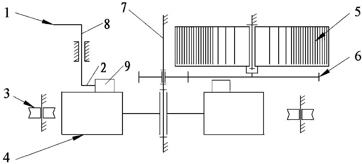
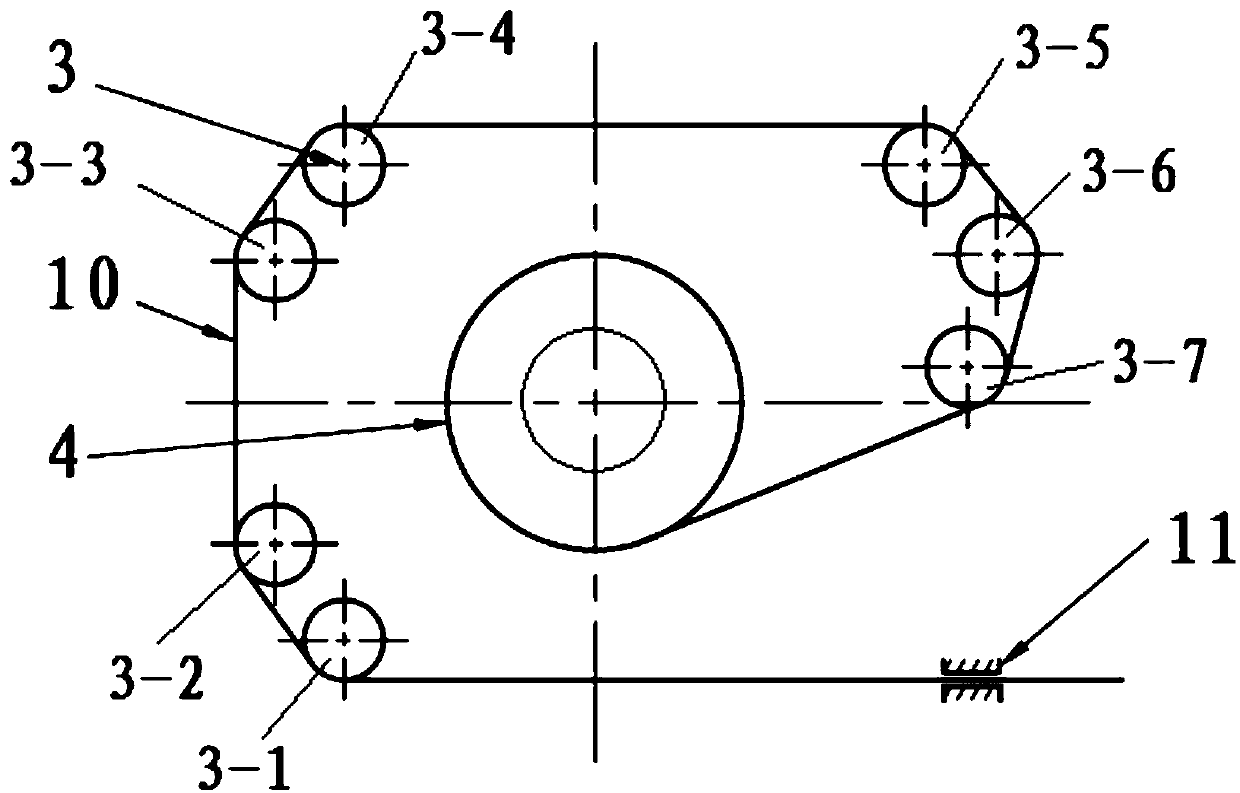
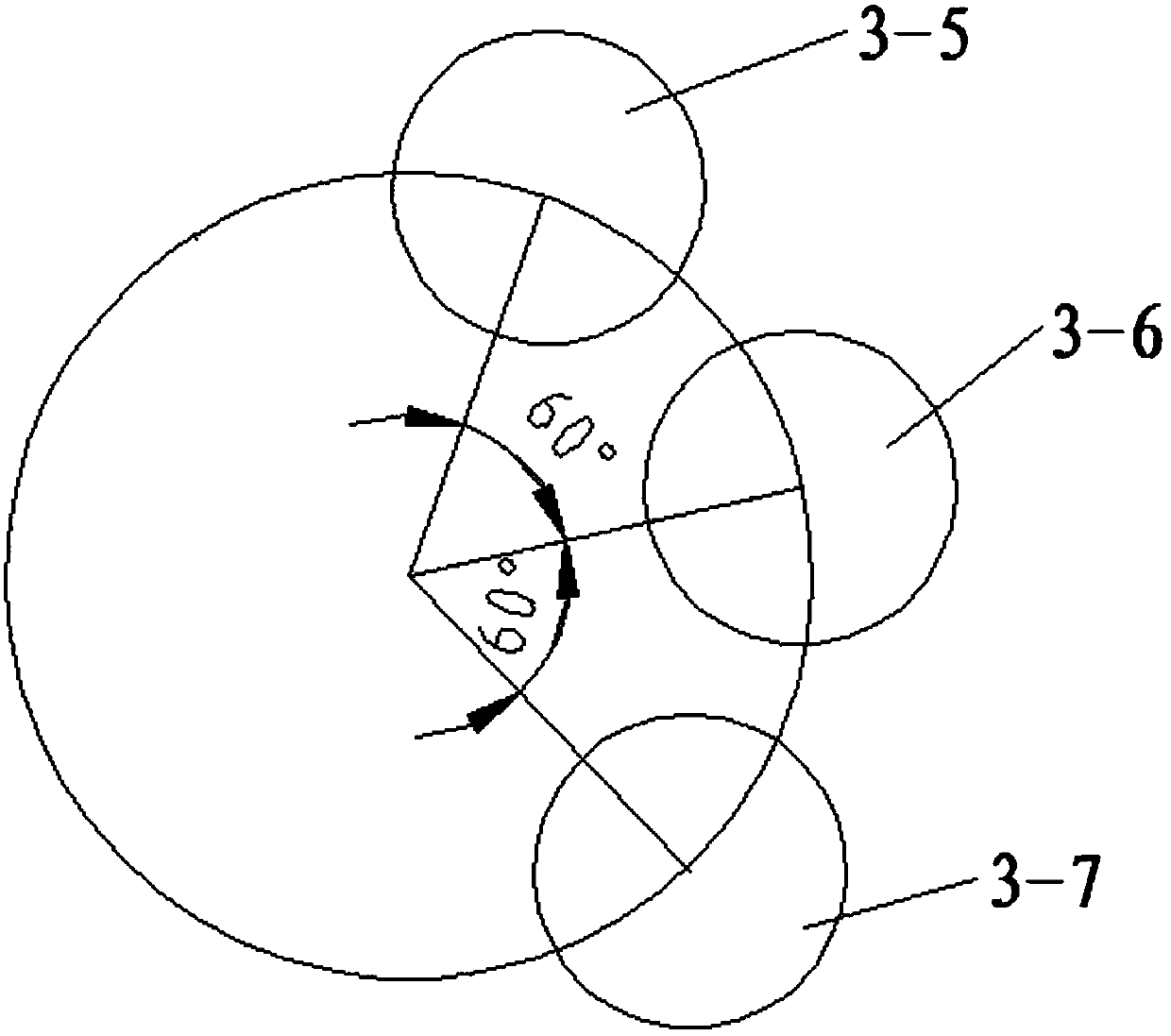

Image

  • Coil-spring-driven steel wire rope winding mechanism for arranging rope based on pulley block
  • Coil-spring-driven steel wire rope winding mechanism for arranging rope based on pulley block
  • Coil-spring-driven steel wire rope winding mechanism for arranging rope based on pulley block

Examples


Embodiment Construction

[0026] Below in conjunction with accompanying drawing and specific embodiment the present invention is described in further detail:

[0027] The present invention adopts the contact type planar scroll spring 5 as the power source, and the contact type planar scroll spring 5 can obtain more working turns under the condition of occupying the same volume. The scroll spring 5 transmits the rotary drive torque to the reel 4 through a pair of transmission gear pairs 6, thereby driving the reel 4 to rotate and complete the action of winding the wire rope 10. The transmission gear pair 6 reduces the driving torque of the scroll spring 5 and simultaneously increases the number of driving circles within the range of the effective driving torque. The scroll spring 5 is used as the power source, no motor is required to provide the turning torque, the introduction of cables is avoided, and the convenience and mobility of the astronauts are enhanced.

[0028] The present invention adopts t...


PUM


Abstract

The invention relates to a coil-spring-driven steel wire rope winding mechanism for arranging a rope based on a pulley block and relates to the field of steel wire rope winding mechanisms for manned spaceflight space environments. The coil-spring-driven steel wire rope winding mechanism comprises a locking rod, a pawl, the rope-arranging assisting pulley block, a winding drum, a scroll spring, a transmission gear pair, a spindle, a pushing shaft and a ratchet wheel; the spindle is vertically located in the middle of the winding mechanism; a driven gear of the transmission gear pair is mountedon the outer wall of the spindle in a sleeving mode; the scroll spring and a driving gear of the transmission gear pair are coaxially and fixedly connected; the locking rod is arranged at the upper end of the pushing shaft in a mode of being perpendicular to the pushing shaft; the pawl is arranged at the lower end of the pushing shaft in a mode of being perpendicular to the pushing shaft; the winding drum is mounted on the outer wall of the spindle in a sleeving mode; the pawl is connected with the ratchet wheel in a matched mode; and the rope-arranging assisting pulley block is arranged on the outer side of the winding drum in an encircling mode. The steel wire rope can be wound orderly by multiple layers and multiple circles; the pulley block is simple in structure and small in occupiedspace; the steel wire rope winding mechanism can have a one-way movement working mode and a two-way movement working mode and adapts to the vacuum space environment, the high temperature space environment, the low temperature space environment and the like.

Description

technical field [0001] The invention relates to the field of a steel wire rope winding mechanism for a manned spaceflight space environment, in particular to a coil spring-driven steel wire rope winding mechanism based on pulley block rope arrangement. Background technique [0002] With the rapid development of my country's aerospace technology and the steady progress of the Shenzhou spacecraft series of missions and the construction of the space station, Chinese astronauts will face frequent on-orbit out-of-vehicle operations, such as out-of-vehicle maintenance of equipment. One of the necessary tools for astronauts to go out of the cabin is the safety tether, which can ensure the reliable connection between the astronaut and the spacecraft. [0003] The safety tethers used by astronauts to leave the cabin are divided into two types: fixed-length safety ropes and retractable safety ropes (adjustable length). Our country has developed mature products for fixed-length safety ...

Claims


Application Information

Patent Timeline
Patent Type & Authority Applications(China)
IPC IPC(8): B66D3/18B66D3/26B66D1/38
CPCB66D1/38B66D3/18B66D3/26B66D2700/0116B66D2700/0183
Inventor 孙启臣曾婷王露斯马永秦俊杰吕立生孙璨
Owner BEIJING SATELLITE MFG FACTORY
Learn More