
Positioning device for gear mechanism

A positioning device and gear mechanism technology, applied in auxiliary devices, workpiece clamping devices, auxiliary welding equipment, etc., can solve the problems of difficult unloading of workpieces, reduced production efficiency, increased costs, etc., to achieve easy positioning and assembly, and ingenious structure Reasonability, work efficiency improvement effect

Pending Publication Date: 2018-02-23
SUZHOU JIANGJIN AUTOMATION TECH
View PDF9 Cites 0 Cited by
  • Summary
  • Abstract
  • Description
  • Claims
  • Application Information

AI Technical Summary

Problems solved by technology

[0003] However, for workpieces that need to be processed, such as frame-type weldments, most positioning devices use fixed positioning blocks or cylinder push-pull positioning blocks. Due to the deformation of the workpiece after welding, the use of fixed positioning blocks will make it difficult to unload the workpiece. Greatly increase the labor intensity of workers and reduce production efficiency. Although the cylinder push-pull positioning block solves the problem that the workpiece is difficult to unload, its cost also greatly increases

Method used


Image

  • Positioning device for gear mechanism
  • Positioning device for gear mechanism
  • Positioning device for gear mechanism

Examples


Embodiment Construction

[0019] The present invention will be described in detail below in conjunction with specific embodiments shown in the accompanying drawings. However, these embodiments are not limited to the present invention, and structural, method, or functional changes made by those skilled in the art according to these embodiments are included within the protection scope of the present invention.

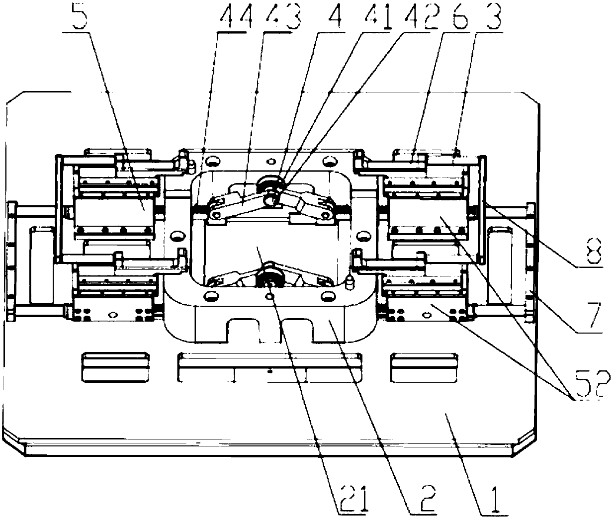
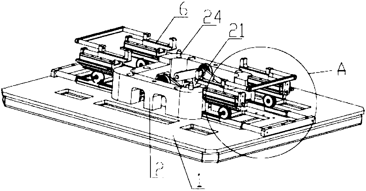
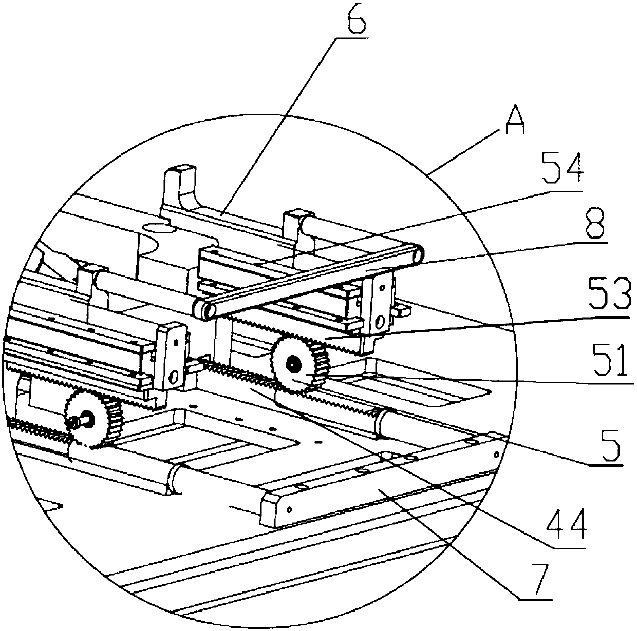
[0020] Such as Figure 1 to Figure 3 As shown, the present invention discloses a gear mechanism positioning device, which includes a base 1 and a limiting block 2 arranged on the base 1, and the limiting block 2 is provided with a receiving space 21 matching the workpiece to be processed ; The position limiting device 2 is also provided with a positioning head 24 that matches the workpiece, and the positioning head 24 can at least partially extend and be placed in the workpiece. The workpiece is over-limited through the accommodating space 21 and the positioning head 24 .

[0021] The base 1 is...


PUM


Abstract

The invention discloses a positioning device for a gear mechanism. The positioning device comprises a base and a limiting block arranged on the base, wherein a containing space matched with a to-be-machined workpiece is formed in the limiting block, and positioning device bodies used for positioning the workpiece in the containing space of the limiting block are further arranged on the base; and the positioning device bodies at least comprise guide wheel assemblies which are arranged in the containing space and can move up and down, wherein the up and down movement of the guide wheel assemblies can drive pressing heads to press or release the workpiece through gear transmission assemblies. The positioning device has the beneficial effects that structure is ingenious and reasonable, the workpiece can be positioned and assembled very conveniently, operation is simple and convenient, special and tedious fastening and dismounting operations are not needed, and working efficiency is greatlyimproved.

Description

technical field [0001] The invention relates to a gear mechanism positioning device, in particular to a positioning device used in machining process. Background technique [0002] With the development and progress of science and technology, a large number of highly automated production lines have been adopted in all walks of life. However, due to the heavy weight of workpieces that need to be processed, such as frame-type weldments, more and more industrial robots are being used. Participate in production in the assembly line workshop. At present, industrial robots usually use various moving manipulators, welding manipulators, automobile painting manipulators, etc. The extensive application of these automated manipulators has doubled the production efficiency of the enterprise, and the product processing quality has also been improved. overflight. It makes the benefits of enterprises grow rapidly, the society develops rapidly, and people's living standards continue to impro...

Claims


Application Information

Patent Timeline
Patent Type & Authority Applications(China)
IPC IPC(8): B23K37/04B25B11/00B25B11/02
CPCB23K37/04B23K37/0443B25B11/00B25B11/02
Inventor 胡志强黄冬梅苏高峰
Owner SUZHOU JIANGJIN AUTOMATION TECH
Learn More