
Automobile headlamp detection method and device

A technology of automobile headlights and detection methods, which is applied in the direction of testing the alignment of automobile headlights, measuring devices, and optical instrument testing, and can solve problems such as difficulty in ensuring measurement accuracy, large errors in measurement methods, and complicated detection devices , to achieve the effect of simple structure, low measurement error and high detection efficiency

Pending Publication Date: 2018-02-16
XIANKEDA TECH KUNMING +1
View PDF10 Cites 10 Cited by
  • Summary
  • Abstract
  • Description
  • Claims
  • Application Information

AI Technical Summary

Problems solved by technology

The described devices all have the following disadvantages: 1) the left and right headlights of the inspected vehicle must be aligned respectively by moving the detector (light box for short) in both horizontal and vertical directions; 2) due to the movement of the light box, The use of vehicle body height sensors, two DC motors (motors), and corresponding control circuits and mechanisms makes the entire detection device complex, complicated to control, and high in cost; 3) and because the distance between the light box and the checked headlight is only or less than 1 meter (the national measurement standard is 10 meters), the resulting error in the measurement method is large, and the measurement accuracy is difficult to guarantee
The method disclosed in this patent is still the same as the above-mentioned patent, which needs to align the left and right headlights of the vehicle under inspection by moving the light box, so there are still problems such as complicated control caused by aligning the detection position , in addition to the complexity and high cost of the whole device, there are also reliability problems

Method used


Image

  • Automobile headlamp detection method and device
  • Automobile headlamp detection method and device
  • Automobile headlamp detection method and device

Examples


Embodiment

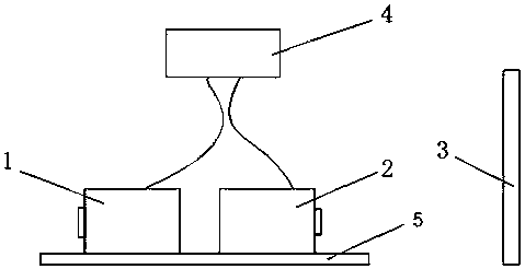
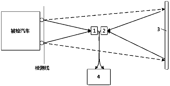
[0039] The present invention is realized like this: firstly do equipment installation.

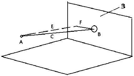
[0040] Install the projection screen 3 of this device in the inspection workshop of a qualified automobile inspection station (in a relatively shading environment), 5-10 meters away from the inspection line. This measurement distance ensures high measurement accuracy from the measurement method and low measurement error. Generally, 5 meters is used, and it can be extended to 10 meters where conditions permit. The projection screen is an ordinary projection screen. The projection screen 3 can be fixedly installed, but it is inconvenient to detect and pass the car, so it is better to use an open screen that can be opened from the middle to the left and right, or it can be an integral lifting screen or a left and right push-pull screen (ground installation track) . Its size is limited to the light spots that can fully cover the left and right headlights of the inspected automobile and irra...


PUM


Abstract

The invention belongs to the technical field of detection. Disclosed is an automobile headlamp detection method, comprising the following steps: 1, acquiring light sources of left and right headlampsof a detected automobile: simultaneously acquiring the light sources of the left and right headlamps of the detected automobile in such a way that a digital camera faces the detected automobile; 2, acquiring projected light spots of the left and right headlamps of the detected automobile: simultaneously acquiring the light spots protected to a screen by the left and right headlamps of the detectedautomobile in such a way that another digital camera backs the detected automobile; 3, processing a digital image: transmitting the data acquired in steps (1) and (2) to a computer by a communicationcable, and detecting the headlamps of the automobile by a matched digital image processing algorithm. The method is completely different from the prior art. During detection, any movement and alignment on the headlamps are not needed, and the detection process is automatically completed, so the method is reliable and low in cost and does not need manual metering. The measurement method ensures high measurement precision and low measurement error.

Description

technical field [0001] The invention relates to a detection method and device for automobile headlights, belonging to the technical field of detection. Background technique [0002] Chinese patent application CN201610017752.8 discloses an intelligent fully automatic vehicle headlight detector. The first-level photosensitive component of the invention can initially locate the area with the highest light intensity of the vehicle headlight, and the second-level photosensitive component can detect The area with the highest light intensity is precisely positioned, so that the light intensity detection element of the detector body can face the area with the highest light intensity to obtain accurate light intensity data. Through the linkage of transmission components, the detector body can be intelligently positioned, and the positioning speed is very fast; the position sensing device provided in the invention can sense whether the car is in the correct detection position, ensurin...

Claims


Application Information

Patent Timeline
Patent Type & Authority Applications(China)
IPC IPC(8): G01M11/06
CPCG01M11/064G01M11/065
Inventor 赵彤丹王威廉余鹏飞王喆民
Owner XIANKEDA TECH KUNMING
Learn More