
System and method for testing light distribution of light spot

A test method and technology of a test system, applied in the field of test systems for spot light distribution, can solve the problems of high maintenance cost, influence of control accuracy and reading accuracy, high equipment manufacturing cost, small volume and area, less hardware and software, Reliable effect

Pending Publication Date: 2018-02-16
深圳百炼光特种照明有限公司
View PDF0 Cites 8 Cited by
  • Summary
  • Abstract
  • Description
  • Claims
  • Application Information

AI Technical Summary

Problems solved by technology

[0002] At present, the methods and devices used to test light distribution on the market are mainly goniophotometers. The principle of the test is to place a light sensor on the light path of the light source or lamp. Since the light of the light source is scattered, the sensor should be fixed. Rotate the light source with a light source, or rotate the sensor with a fixed light source, test the light intensity of the light source or lamp at each solid angle, and then draw the light distribution curve through the software, and get the light intensity distribution, which cannot directly test the light intensity of a certain area. Illumination value
In addition, this test method requires a control device that can precisely control the rotation angle, and the instrument occupies a large area. For example, the length of the goniophotometer device for testing street lamps can reach 6 to 10 m. The manufacturing cost of the equipment is very high, and it is inconvenient to use. Maintenance costs are also high
At the same time, this device cannot be used to test the illuminance distribution accurate to the millimeter level on a circular spot with a spot size of only 160mmx80mm or a diameter of only 200mm.
The diameter of the light sensor head of an ordinary illuminance meter ranges from 10mm-20mm, which measures the average illuminance projected on the entire light sensor, and cannot be accurate to the illuminance value on the size of millimeters
During the test, the optical sensor needs to be manually moved. The control accuracy and reading accuracy are greatly affected by human factors. They can only be used as a very rough reference and cannot be accurately measured in advance.

Method used


Image

  • System and method for testing light distribution of light spot
  • System and method for testing light distribution of light spot
  • System and method for testing light distribution of light spot

Examples


Embodiment 1

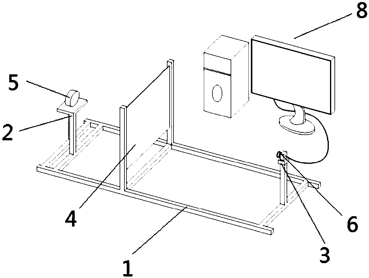
[0038] Such as Figure 1~Figure 8 Shown, a kind of test method of spot light distribution, it comprises the following steps:

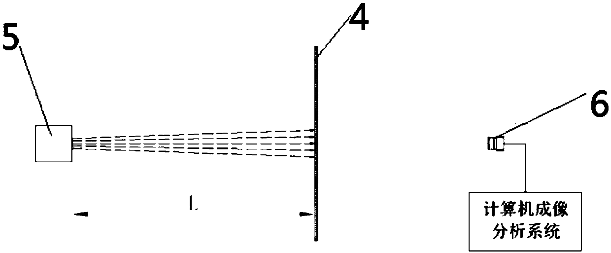
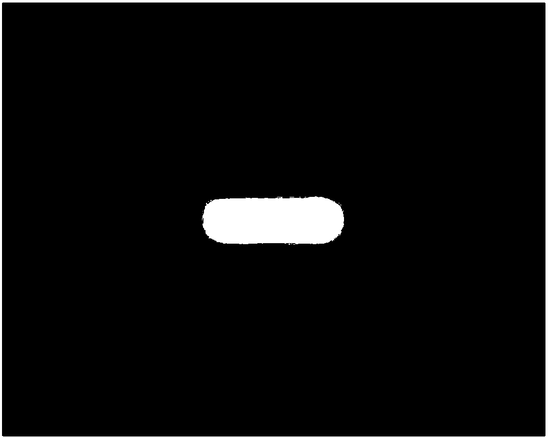
[0039] Such as figure 1 and figure 2 As shown, in step S1, the light emitted by the light source product 5 to be tested is irradiated onto the translucent imaging plate 4, and bright spots illuminated by the light source product 5 to be tested appear on the other side of the translucent imaging plate 4, as shown in FIG. image 3 As shown, a camera 6 is placed on the other side of the translucent imaging plate 4 relative to the light source product 5 to be tested, and the camera 6 takes pictures of bright spots. After the imaging analysis system of the computer 8, the distance L of the light source product 5 to be tested is calculated. Spot brightness distribution and size information; wherein, preferably, the range of L is 0.5-1m.

[0040] Step S2, placing a ruler 7 on the side of the translucent imaging plate 4 facing the camera 6, such as Figur...

Embodiment 2

[0048] Such as figure 1 and figure 2 As shown, a test system for spot light distribution, which adopts the test method for spot light distribution as described above for testing, includes a test frame 1 and a computer 8, and the two ends of the test frame 1 are respectively provided with product placement racks 2 and a camera placement frame 3, the middle part of the test frame 1 is provided with a translucent imaging plate 4, the light source product 5 to be tested is placed on the product placement frame 2, the camera 6 is placed on the camera placement frame 3, and the translucent imaging The plate 4 is located on the vertical plane connecting the light source product 5 to be tested and the camera 6; the light emitted by the light source product 5 to be tested is imaged on the translucent imaging plate 4; The image is connected with the computer 8, and the imaging analysis system of the computer 8 obtains the information of the camera 6 for analysis. The central axis of ...


PUM


Abstract

The invention provides a system and method for testing the light distribution of light spot. The method herein includes the following steps: projecting light that is emitted from a product to an imaging plate, wherein light spot that is projected by the product appears on the other side of the imaging plate, placing a camera on the other side of the product of the imaging plate, the camera takingphotos of the light spot, conducting imaging analysis on the light distribution and size information of the light spot at a L-distance from the product through a computer; placing a scale on the sideof the imaging plate facing the camera, obtaining the corresponding relation between the scale on the vertical surface at a L-distance from the product and the pixels of the camera; adjusting the calibrating a brightness reference, obtaining a function relation between the brightness at a L-distance from a light source and the gray scale of the camera; and obtaining the brightness of each pixel point of the imaged light spot and the size and position information of each pixel point. According to the invention, the technical solution requires less hardware and software, and the test system takes less volume and area. The test system is movable, and requires no calibration after being moved. The test system is easy and fast to implement.

Description

technical field [0001] The invention belongs to the technical field of special lighting, and in particular relates to a test system and a test method for spot light distribution. Background technique [0002] At present, the methods and devices used to test light distribution on the market are mainly goniophotometers. The principle of the test is to place a light sensor on the light path of the light source or lamp. Since the light of the light source is scattered, the sensor should be fixed. Rotate the light source with a light source, or rotate the sensor with a fixed light source, test the light intensity of the light source or lamp at each solid angle, and then draw the light distribution curve through the software, and get the light intensity distribution, which cannot directly test the light intensity of a certain area. illuminance value. In addition, this test method requires a control device that can precisely control the rotation angle, and the instrument occupies ...

Claims


Application Information

Patent Timeline
Patent Type & Authority Applications(China)
IPC IPC(8): G01J1/00
CPCG01J1/00
Inventor 肖尚平余海军
Owner 深圳百炼光特种照明有限公司
Learn More