
Automobile synchronizer

A synchronizer and automobile technology, applied in the direction of clutches, mechanical drive clutches, mechanical equipment, etc., can solve the problems of reducing vehicle power and fuel economy, inconvenient synchronizer shifting, slowing down the life of the transmission, etc., to reduce the number of synchronizers. Effects of failure rate, low inertia, and reduced number of parts

Pending Publication Date: 2018-02-16
江苏追日汽车同步器有限公司
View PDF0 Cites 1 Cited by
  • Summary
  • Abstract
  • Description
  • Claims
  • Application Information

AI Technical Summary

Problems solved by technology

At present, it is inconvenient to use the synchronizer to change gears. The gears and shafts are strongly impacted during the gear change, which slows down the life of the transmission, is labor-intensive, and reduces the power and fuel economy of the car.

Method used


Image

  • Automobile synchronizer
  • Automobile synchronizer
  • Automobile synchronizer

Examples


Embodiment Construction

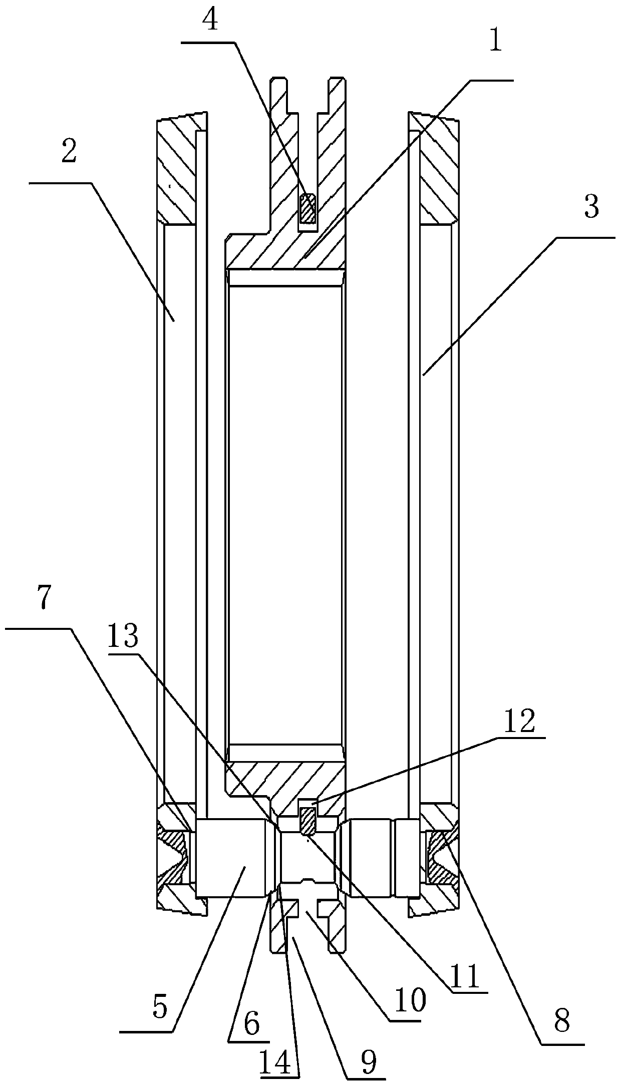
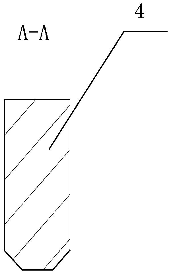
[0011] exist figure 1 with figure 2 Among them, the present invention provides an automobile synchronizer, which is provided with a sliding tooth sleeve 1, a synchronous cone ring I2, a synchronous cone ring II3, a positioning circlip 4 and a lock shaft 5, and the synchronous cone ring I2 and the synchronous cone ring II3 are located at the sliding On both sides of the gear sleeve 1, there are several locking holes 6 evenly distributed in the circumferential direction of the sliding gear sleeve 1, and three locking holes 6 are evenly distributed in the circumferential direction of the sliding gear sleeve 1 in this embodiment, and the synchronous cone ring I2 There are several locking holes I7 evenly distributed in the circumferential direction of the synchronous cone ring I2 in this embodiment. There are three locking holes I7 evenly distributed in the circumferential direction of the synchronous cone ring II3. Three locking holes II8 are evenly distributed in the circumfere...


PUM


Abstract

The invention discloses an automobile synchronizer. Positions of locking pin holes (6) correspond to those of first locking pin holes (7) and those of second locking pin holes (8), and a sliding gearsleeve (1), a first synchronous conical ring (2) and a second synchronous conical ring (3) are connected into a whole by inserting locking pins (5) into the locking pin holes (6), the first locking pin holes (7) and the second locking pin holes (8); multiple locating ring slots (10) are formed in the groove bottom of a shifting fork groove (9) in the radial direction, and each locating ring slot (10) corresponds to one locking pin hole (6) of the sliding gear sleeve (1); a locating slot (11) is formed in the middle of each locking pin (5), and each locating slot (11) corresponds to one locating ring slot (10); and locating clamping slots (12) are formed in the groove bottom of the shifting fork groove (9), each locating snap spring (4) is embedded into the corresponding locating clamping slot (12), the outer side of each locating snap spring (4) is located in the corresponding locating slot (11), and a locking surface (14) of each locking pin (5) corresponds to one locking angle (13) of the corresponding locking pin hole (6).

Description

technical field [0001] The invention relates to an automobile synchronizer. Background technique [0002] Automobile synchronizer is a key component of mechanical gear transmission. The synchronizer is responsible for shifting gears and transmitting torque. It is a key and vulnerable part in the gearbox. At present, it is inconvenient to use the synchronizer to shift gears. When shifting gears, the gears and shafts are strongly impacted, which slows down the life of the transmission, is labor-intensive, and reduces the power and fuel economy of the car. Contents of the invention [0003] The invention provides an automobile synchronizer, which not only realizes positioning when the synchronizer is in neutral. The number of parts is reduced, the failure rate of the synchronizer is reduced; the difficulty of processing the synchronizer is reduced, and the production cost is reduced. [0004] The present invention adopts the following technical solutions: an automobile sync...

Claims


Application Information

Patent Timeline
Patent Type & Authority Applications(China)
IPC IPC(8): F16D23/02
CPCF16D23/02
Inventor 李汉祥
Owner 江苏追日汽车同步器有限公司
Learn More