
Abrasion-resisting ball hinge controlled on basis of slider-crank mechanism

A crank-slider mechanism and hinge technology, which is applied in the field of ball hinges, can solve the problems of shortening the service life of hinges, increasing costs, and wear of rolling balls.

Inactive Publication Date: 2018-02-16
车成凯
View PDF0 Cites 0 Cited by
  • Summary
  • Abstract
  • Description
  • Claims
  • Application Information

AI Technical Summary

Problems solved by technology

[0002] After the current existing ball hinges are used for a period of time, the rolling balls in the hinge will be worn out, and the worn balls will lose the purpose of hinged two hinges, and the hinge at this time will be If it loses its function, the service life of the hinge at this time will be greatly reduced. In order to avoid this situation, the traditional improvement is to carry out special heat treatment on the rolling ball, or replace the rolling ball after the ball is worn, so as to achieve recovery. The purpose of using the function of the hinge will greatly increase the cost at this time, so in order to avoid this situation, it is necessary to design a wear-resistant ball hinge based on the control of the slider crank mechanism.

Method used


Image

  • Abrasion-resisting ball hinge controlled on basis of slider-crank mechanism
  • Abrasion-resisting ball hinge controlled on basis of slider-crank mechanism
  • Abrasion-resisting ball hinge controlled on basis of slider-crank mechanism

Examples


Embodiment Construction

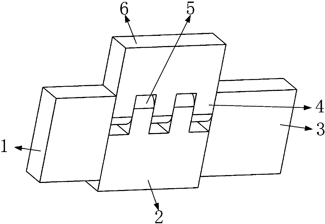
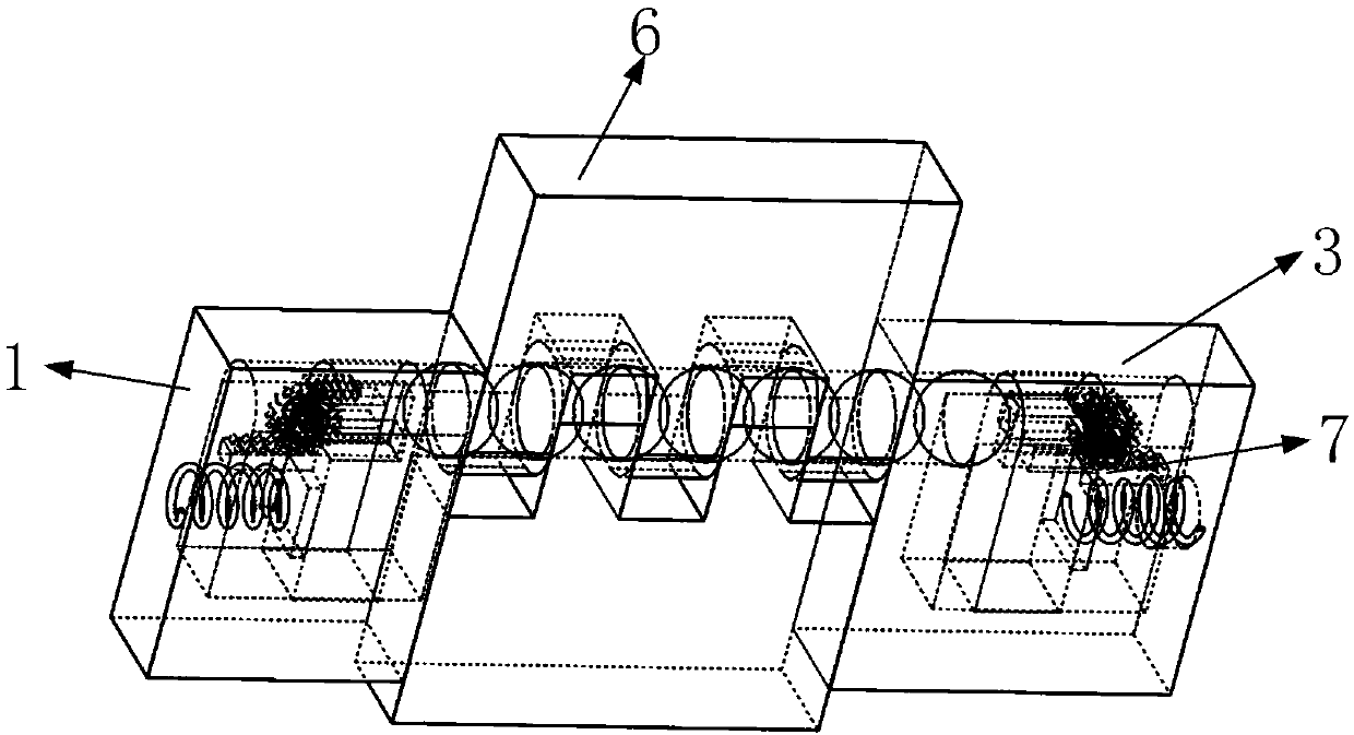
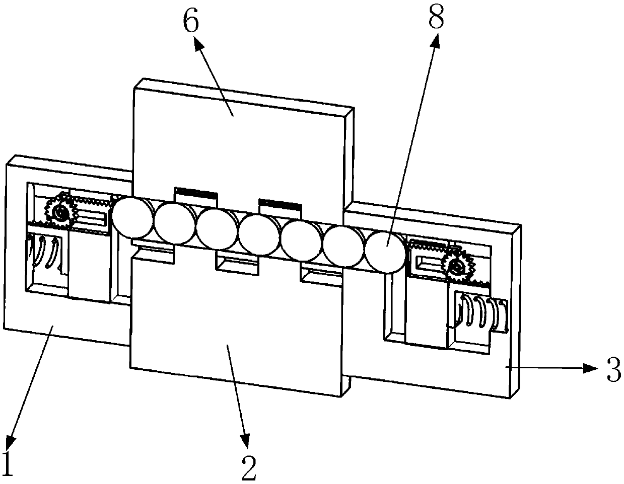
[0050] Such as figure 1 , 2 , 3, it includes the first fixed block 1, the first hinge 2, the second fixed block 3, the first lug 4, the second lug 5, the second hinge 6, the adjustment mechanism 7, the rolling ball 8 , the first housing chamber 9, the round hole 10, the second housing chamber 11, the spring hole 12, such as Figure 4 , 5 As shown, there is a first accommodating chamber 9 on the side of the first fixed block 1; as Figure 8 As shown, the side of the first hinge 2 is installed on the side of the first accommodating cavity 9 of the first fixed block 1; Figure 8 As shown, two second lugs 5 are sequentially installed on the upper end surface of the first hinge 2; as Figure 6 , 7 As shown, there is a round hole 10 on the side of the second fixed block 3, and a second accommodating cavity 11 is opened on the end face of the round hole 10; Figure 7 As shown, there is a spring hole 12 on the end surface of the second accommodation cavity 11; the side of the ro...


PUM


Abstract

The invention belongs to the technical field of ball hinges, in particular to an abrasion-resisting ball hinge controlled on the basis of a slider-crank mechanism. The abrasion-resisting ball hinge comprises a first fixing block, a first hinge, a second fixing block, a first support lug, a second support lug, a second hinge, an adjusting mechanism and the like. Convenient containing of the adjusting mechanism is the function of forming of a first containing cavity in the side face of the first fixing block. Convenient containing of a rolling ball is the function of forming of a circular hole in the side face of the second fixing block, and convenient installation of the adjusting mechanism is the function of forming of a second containing cavity in the end face of the circular hole. Compared with a traditional ball hinge, adjustment of rolling balls in the first support lug and the second support lug is the function of the adjusting mechanism, the intersection face of the second hingeand the first fixing block constantly coincides with the center face of the corresponding rolling ball, and the intersection face of the first support lug and the second support lug constantly coincides with the center face of the corresponding rolling ball; the hinge can be constantly used; and accordingly the purpose of abrasion-resisting usage of the ball hinge is achieved.

Description

technical field [0001] The invention belongs to the technical field of ball hinges, in particular to a wear-resistant ball hinge based on the control of a slider crank mechanism. Background technique [0002] After the current existing ball hinges are used for a period of time, the rolling balls in the hinge will be worn out, and the worn balls will lose the purpose of hinged two hinges, and the hinge at this time will be If it loses its function, the service life of the hinge at this time will be greatly reduced. In order to avoid this situation, the traditional improvement is to carry out special heat treatment on the rolling ball, or replace the rolling ball after the ball is worn, so as to achieve recovery. The purpose of using the function of the hinge will greatly increase the cost at this time, so in order to avoid this situation, it is necessary to design a wear-resistant ball hinge based on the control of the slider crank mechanism. [0003] The present invention d...

Claims


Application Information

Patent Timeline
Patent Type & Authority Applications(China)
IPC IPC(8): F16C11/06
CPCF16C11/0609F16C11/0647
Inventor 车成凯
Owner 车成凯
Learn More