Anti-deformation-type multi-layer wood composite structure with heating function

A composite structure, anti-deformation technology, applied in the field of flooring, can solve problems such as poor applicability and inconvenient interception, and achieve the effects of improving durability, avoiding curling, and expanding the scope of application

Inactive Publication Date: 2018-02-16
SICHUAN XINGZHI ZHIHUI INTPROP OPERATION CO LTD
View PDF6 Cites 2 Cited by
  • Summary
  • Abstract
  • Description
  • Claims
  • Application Information

AI Technical Summary

Problems solved by technology

[0004] The technical problem to be solved by the present invention is: the length, width and height of the existing whole floor are fixed, it is not easy to intercept during installation, and the applicability is not strong. The purpose is to provide an anti-change form heating multi-layer Wooden composite structure, which can realize long and short cutting without affecting its own function and effect, and has a wider application range

Method used


Image

  • Anti-deformation-type multi-layer wood composite structure with heating function
  • Anti-deformation-type multi-layer wood composite structure with heating function

Examples


Embodiment 1

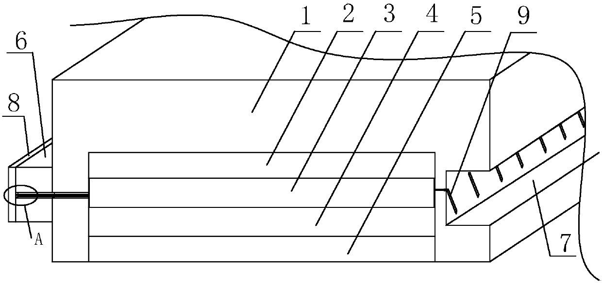
[0025] A form of anti-alteration heating of multi-layer wood composite structures such as figure 1 As shown, it includes a wooden floor body 1, a heat conduction layer 2, a heat generation layer 3, a reflective layer 4 and a heat insulation layer 5 arranged under the wooden floor body 1 in sequence.

[0026] The wooden floor body 1 is in the shape of a cuboid, and the middle part of the bottom of the wooden floor body 1 has a hollow body arranged along the direction of the long side. Inside the cavity, and the side wall of one long side of the wooden floor body 1 is provided with a protruding strip 6 with the same length as the wooden floor body 1, and the side wall of the other long side of the wooden floor body 1 is provided with a The protruding strip 6 matches the groove 7, and the protruding strip 6 and the groove 7 are both provided with a connecting cable 10 passing through the wooden floor body 1 and communicating with the heating layer 3 .

Embodiment 2

[0028] The difference between this embodiment and Embodiment 1 is that the setting method at the position of the connecting cable 10 is optimized in this embodiment, and the specific settings are as follows:

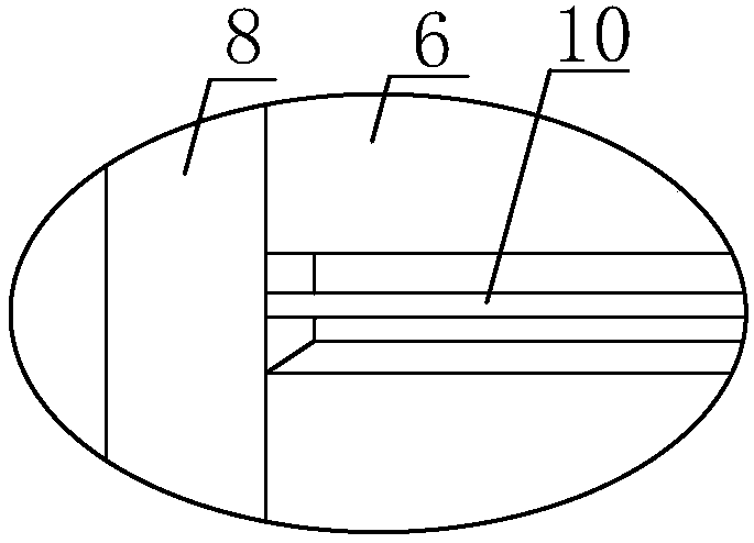
[0029] One side of the protruding strip 6 is fixed on the wooden floor body 1, and the other side of the protruding strip 6 is provided with a guide piece 8, which communicates with the heating layer 3 through a connecting cable 10; There is a connecting piece 9, and the connecting piece 9 is also communicated with the heating layer 3 through another connecting cable 10.

[0030] The length of the guide piece 8 is the same as the length of the wooden floor body 1; the connecting piece 9 is fixed on the first connecting piece connected with the connecting cable 10 on the wooden floor body 1 by one end, and one end is connected with the other end of the first connecting piece. It consists of a fixed second connecting piece, and the angle between the second connecting piece...

Embodiment 3

[0032] The difference between this embodiment and Embodiment 2 is that the structural settings are optimized, and the specific settings are as follows:

[0033] The angle between the second connecting piece and the first connecting piece is set at 95-100 degrees. The heating layer 3 is a nickel-chromium alloy heating layer. The heat conduction layer 2 is made of aerospace grade aluminum alloy material.


PUM


Abstract

The invention discloses an anti-deformation-type multi-layer wood composite structure with a heating function. The problems that as for an existing overall floor, the length, width and the height areconstant, cutting is inconvenient in mounting, and the adaptability is low are solved. The anti-deformation-type multi-layer wood composite structure comprises a wood floor body and further comprisesa heat conduction layer, a heating layer, a reflecting layer and a heat insulation layer which are sequentially arranged below the wood floor body. The wood floor body is in a cuboid shape, a cavity body is formed in the middle portion of the bottom of the wood floor body in the long edge direction. The heat conduction layer, the heating layer, the reflecting layer and the heat insulation layer are arranged in the cavity body, the side wall of one long edge of the wood floor body is provided with a convex strip with the same length as the wood floor body, and the side wall of the other long edge of the wood floor body is provided with a groove matched with the convex strip. Connecting cables which penetrate through the wood floor body and communicate with the heating layer are arranged onthe convex strip and the groove correspondingly. The anti-deformation-type multi-layer wood composite structure with the heating function has the advantages that the length can be cut, and the groundheating function is not affected after cutting.

Description

technical field [0001] The invention belongs to the field of floors, and in particular relates to an anti-deformation heating multi-layer wooden composite structure. Background technique [0002] People have done extensive research on floor heating. Generally speaking, the electric heating material is arranged in the floor, and the purpose of heating is achieved by energizing the electric heating material in the floor, so that the floor generates heat for heating. Since the heat transfer of the floor itself is not very good, some floors in the prior art are also equipped with heat-conducting materials, which further conduct the heat generated by the electric heating materials to various parts of the floor, thereby providing a uniform space for the entire floor. heating. [0003] There are two installation methods for underfloor heating in the prior art. One is to install the heating part separately from the floor surface, and the other is to install it as a whole. The sepa...

Claims


Application Information

Patent Timeline
IPC IPC(8): E04F15/02F24D13/02
Inventor 谭逢林
Owner SICHUAN XINGZHI ZHIHUI INTPROP OPERATION CO LTD
Why Eureka
Try Eureka