
Heavy numerical control machine tool thermal error compensation control system based on CPS (Cyber-Physical Systems) and thermal error compensation method

A heavy-duty CNC machine tool, compensation control technology, applied in the general control system, control/adjustment system, computer control, etc., can solve the problems of insufficient network communication capabilities, low intelligence, poor independence, etc., to achieve exquisite design and versatility Strong, easily replaceable effect

Active Publication Date: 2018-02-16
WUHAN UNIV OF TECH
View PDF9 Cites 12 Cited by
  • Summary
  • Abstract
  • Description
  • Claims
  • Application Information

AI Technical Summary

Problems solved by technology

[0006] Aiming at the disadvantages of the existing CNC machine tool thermal error compensation control system, such as poor independence and versatility, insufficient network communication capabilities, and low intelligence, the present invention proposes a heavy-duty CNC machine tool thermal error compensation control system and thermal error compensation control system based on CPS architecture. compensation method

Method used


Image

  • Heavy numerical control machine tool thermal error compensation control system based on CPS (Cyber-Physical Systems) and thermal error compensation method
  • Heavy numerical control machine tool thermal error compensation control system based on CPS (Cyber-Physical Systems) and thermal error compensation method
  • Heavy numerical control machine tool thermal error compensation control system based on CPS (Cyber-Physical Systems) and thermal error compensation method

Examples


Embodiment Construction

[0048] The present invention will be further described in detail below in conjunction with the accompanying drawings and specific embodiments.

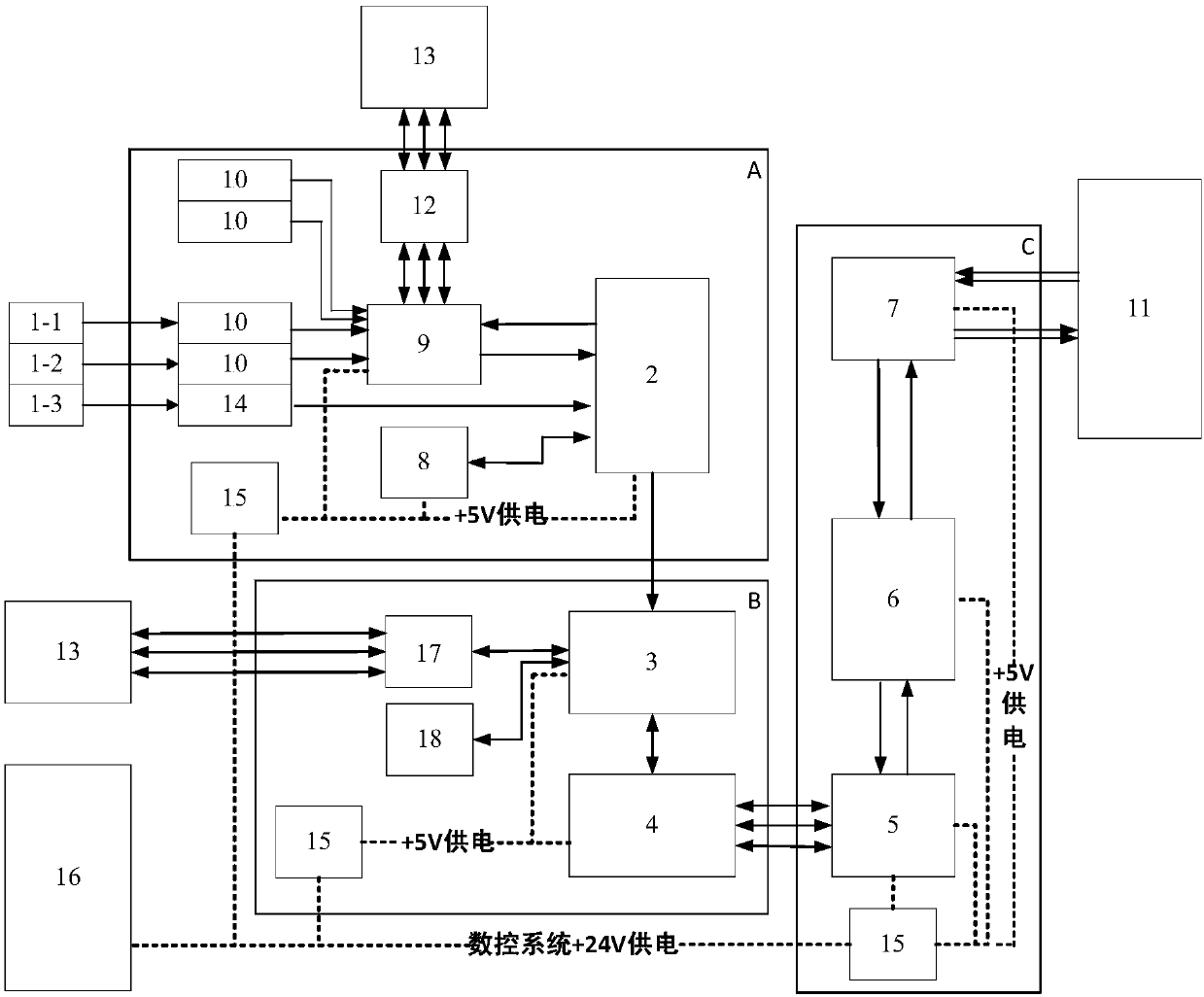
[0049] Such as figure 1 As shown, a CPS-based thermal error compensation control system for heavy-duty CNC machine tools in the present invention includes an embedded acquisition card A, an operation controller B, a CNC connector C and a system power supply.

[0050] The embedded acquisition card A is placed in the electrical cabinet of the CNC machine tool, including the physical layer and network layer in the CPS architecture. The embedded acquisition card A is used to collect the temperature information of the machine tool measuring point and the displacement thermal error of the tool tip of the machine tool spindle, upload the collected data to the cloud server through the wireless network, and send the data to the operation controller B after preprocessing.

[0051] The embedded acquisition card A includes a sensor 1 , a data pr...


PUM


Abstract

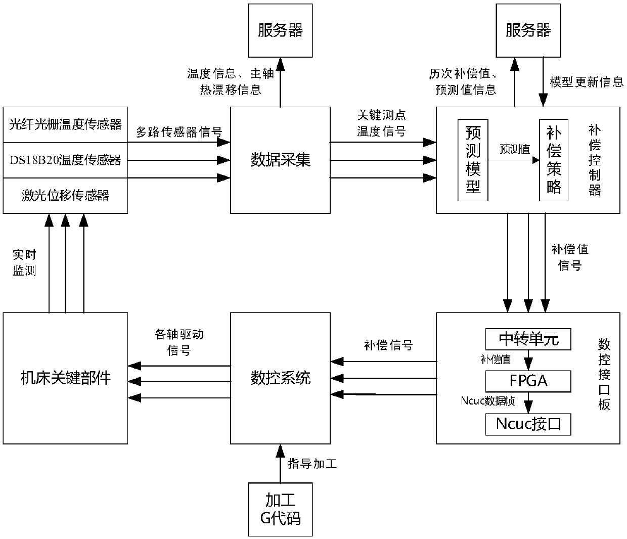
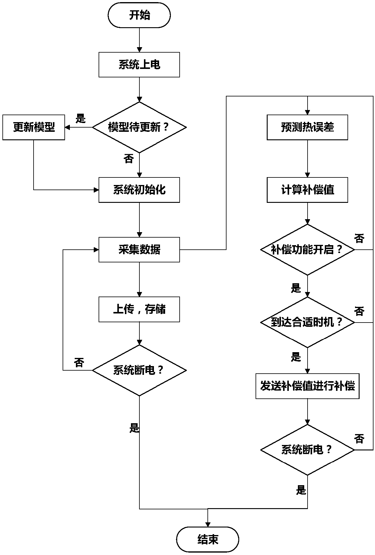
The invention discloses a heavy numerical control machine tool thermal error compensation control system based on CPS (Cyber-Physical Systems) and a thermal error compensation method. The thermal error compensation control system comprises an embedded acquiring card, an operation controller and a numerical control connector, wherein the embedded acquiring card is used for acquiring the temperatureinformation of measuring points of a machine tool and the displacement thermal errors of a main shaft tool tip of the machine tool and sending data to the operation controller after preprocessing; the operation controller is used for substituting the received temperature data into a prediction mathematical model to calculate thermal error prediction values, processing the thermal error predictionvalues into real-time compensation values according to formulated compensation strategies and uploading the thermal error prediction values and the real-time compensation values to a cloud server through a wireless network, wherein the prediction mathematical model and the compensation strategies are remotely updated through the wireless network; and the numerical control connector is used for inputting the received real-time compensation values to a machine tool numerical control system through a NCUC bus, and the machine tool numerical control system reads the real-time compensation valuesin operation and processing of G codes, and controls of the machine tool to move in the X axis, the Y axis and the Z axis.

Description

technical field [0001] The invention relates to the technical field of thermal error compensation of numerical control machine tools, in particular to a thermal error compensation control system and thermal error compensation method of heavy numerical control machine tools based on CPS. Background technique [0002] Heavy-duty CNC machine tools are an important part of today's high-end equipment manufacturing industry, and are the cornerstone of national defense industry and machinery manufacturing. The machining accuracy of heavy-duty CNC machine tools represents the industrial development level of a country. With the proposal of the "Made in China 2025" strategy, the requirement to improve the machining accuracy of CNC machine tools is becoming more and more urgent. Due to its large size and large stroke, heavy-duty machine tools are susceptible to thermal errors due to the influence of internal and external heat sources. A large number of studies have shown that among al...

Claims


Application Information

Patent Timeline
Patent Type & Authority Applications(China)
IPC IPC(8): B23Q11/00G06F17/50G05B19/404
CPCB23Q11/0007G05B19/404G06F30/20G06F2119/08
Inventor 娄平李炆峰胡建民严俊伟刘泉周祖德
Owner WUHAN UNIV OF TECH
Learn More