Efficient steel pipe machining device

A technology for processing equipment and steel pipes, applied in positioning equipment, metal processing equipment, metal processing machinery parts, etc., can solve the problems of large overall size of processing equipment, high spindle center, and heavy steel pipe weight, reducing labor intensity of workers and improving The effect of work efficiency and simple structure

Inactive Publication Date: 2018-02-16
郭丹枫
View PDF5 Cites 0 Cited by
  • Summary
  • Abstract
  • Description
  • Claims
  • Application Information

AI Technical Summary

Problems solved by technology

[0002] When cutting or processing the outer circle or inner hole near the end of the steel pipe, in order to facilitate positioning and clamping, a pair of V-shaped blocks that move in the front and rear directions are often used to clamp the steel pipe to ensure that the center height and center position of the steel pipe remain unchanged. , but due to the heavy weight of the steel pipe, on the one hand, the required clamping force is large; on the other hand, in order to adapt to the positioning, clamping and processing of steel pipes with different diameters, the center height of the spindle is often large, resulting in a large overall size of the processing equipment

Method used


Image

  • Efficient steel pipe machining device
  • Efficient steel pipe machining device
  • Efficient steel pipe machining device

Examples


Embodiment Construction

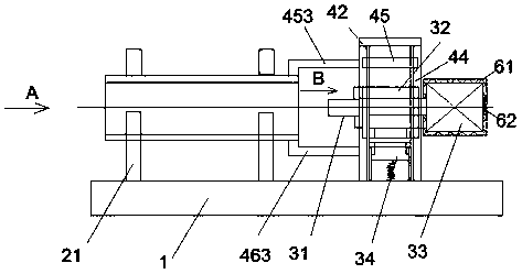
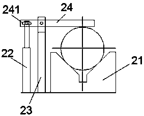
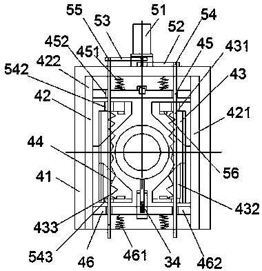
[0029] Such as Figure 1-Figure 8 As shown, a high-efficiency steel pipe processing device of the present invention includes a frame 1, a steel pipe clamping unit, a spindle unit and a spindle adjustment unit, the steel pipe clamping unit is fixed on the upper surface of the frame 1, and the spindle The unit is installed in the middle of the main shaft adjustment unit, and the main shaft adjustment unit is installed on the upper surface of the frame on the right side of the steel pipe clamping unit and can slide in the left and right directions. The main shaft unit includes a support sleeve 32, a main shaft 31, a motor 33 and a support seat assembly 34, the support seat assembly 34 is fixed on the upper surface of the frame 1, the support sleeve 32 is placed on the top surface of the support seat assembly 34, and the main shaft 31 is supported and installed on the Inside the supporting sleeve 32, the motor 33 is fixed on the right end of the supporting sleeve 32 and the shaft ...


PUM


Abstract

The invention discloses an efficient steel pipe machining device. The efficient steel pipe machining device comprises a rack, a steel pipe clamping unit, a main shaft unit and a main shaft adjusting unit. The steel pipe clamping unit is fixed to the upper surface of the rack, the main shaft unit is arranged at the middle portion of the main shaft adjusting unit, and the main shaft adjusting unit is arranged on the upper surface of the part, on the right side of the steel pipe clamping unit, of the rack and can slide in the left-right direction. According to the efficient steel pipe machining device, automatic adjustment on the up-down position of the main shaft unit can be rapidly achieved, accordingly, centering of the main shaft unit and a center line of a steel pipe is rapidly achieved,and the main shaft unit is automatically clamped. The integral structure is simple, automatic control is achieved, operation is convenient and fast, the work efficiency is improved, and machining ofsteel pipes different in diameter can be achieved.

Description

technical field [0001] The invention relates to the technical field of steel pipe processing equipment, in particular to an efficient steel pipe processing device. Background technique [0002] When cutting or processing the outer circle or inner hole near the end of the steel pipe, in order to facilitate positioning and clamping, a pair of V-shaped blocks that move in the front and rear directions are often used to clamp the steel pipe to ensure that the center height and center position of the steel pipe remain unchanged. , but due to the heavy weight of the steel pipe, on the one hand, the required clamping force is large, and on the other hand, in order to adapt to the positioning, clamping and processing of steel pipes with different diameters, the center height of the spindle is often large, resulting in a large overall size of the processing equipment. Contents of the invention [0003] The technical problem to be solved by the present invention is to provide an eff...

Claims


Application Information

Patent Timeline
IPC IPC(8): B23Q3/06
CPCB23Q3/064
Inventor 郭丹枫马洁
Owner 郭丹枫
Why Eureka
Try Eureka