Novel power tube device

A power pipe and a new type of technology, applied in the field of new power pipe devices, can solve the problems of limited clamping and fixing force, influence on the quality of the threading, poor fixing effect, etc., and achieve the effects of convenience and accuracy, improving threading efficiency and simple structure

Inactive Publication Date: 2018-05-25
宁波市鄞州明联物联科技有限公司
View PDF0 Cites 0 Cited by
  • Summary
  • Abstract
  • Description
  • Claims
  • Application Information

AI Technical Summary

Problems solved by technology

During the use of the power tube, it is often necessary to thread the inner walls at both ends, and then tighten the thread to lengthen the connection. Due to the heavy weight of the power tube, the clamping force required is relatively large, and the clamping and fixing force of the traditional threading machine is limited, and the fixing effect is limited. Poor, it is easy to shake during the threading process and seriously affect the threading quality

Method used


Image

  • Novel power tube device
  • Novel power tube device
  • Novel power tube device

Examples


Embodiment Construction

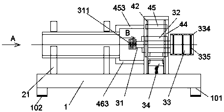
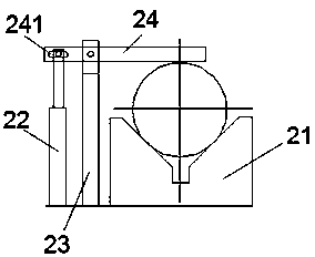
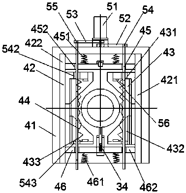
[0026] Such as Figure 1-Figure 8 As shown, a new type of power pipe device of the present invention includes a mounting frame 1, a setting part, a threading part and a clamping part, the setting part is fixed on the upper surface of the mounting frame 1, and the threading part is installed on The middle end of the clamping part, the clamping part is installed on the upper surface of the mounting frame on the right side of the placement part and can slide in the left and right direction, the bottom of the mounting frame 1 is provided with a supporting angle 101, each of the The bottoms of the supporting angles 101 are equipped with anti-slip pads 102, which can effectively prevent the phenomenon of unstable support caused by slipping due to wet and slippery ground, thereby improving the stability during support. The threaded part includes a support sleeve 32, The rotating pin shaft 31, the first motor 33 and the support seat assembly 34, the support seat assembly 34 is fixed o...


PUM


Abstract

The invention discloses a novel power tube device which comprises a mounting rack, an arrangement part, a fiber sleeving part and a firmly clamping part. The arrangement part is fixed in the upper surface of the mounting rack, the fiber sleeving part is installed in the middle end of the firmly clamping part, and the firmly clamping part is mounted in the upper surface of the mounting rack and onthe right of the arrangement part, and can slide along the left and right direction. The novel power tube device is simple in structure, automatic in control and convenient to operate, and can realizealigning and adjusting automatically, and improve the fiber sleeving accuracy and efficiency.

Description

technical field [0001] The invention relates to the technical field of electric equipment, in particular to a novel electric tube device. Background technique [0002] Power pipes are often used in power laying. They are mainly used to store cables or wires and then bury them to play the role of corrosion resistance and oxidation resistance. During the use of the power tube, it is often necessary to thread the inner walls at both ends, and then tighten the thread to lengthen the connection. Due to the heavy weight of the power tube, the clamping force required is relatively large, and the clamping and fixing force of the traditional threading machine is limited, and the fixing effect is limited. Poor, it is very easy to shake during the threading process and seriously affect the threading quality. Contents of the invention [0003] The technical problem to be solved by the present invention is to provide a new power tube device, which can solve the above-mentioned problem...

Claims


Application Information

Patent Timeline
Patent Type & Authority Applications(China)
IPC IPC(8): H02G3/04
CPCH02G3/0406
Inventor 姚瑞波
Owner 宁波市鄞州明联物联科技有限公司
Why Eureka
Try Eureka